| Load |
Select the load case or load group to which this load will be added.
Tip: The
current load case or group is the default selection. This is displayed
in the program status bar and can be changed on the
View ribbon tab in the Active
Load group.
|
| Moment type
|
Select the type of distributed
moment:
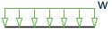
- Uniform - a
moment which is constant in magnitude along the entire member length
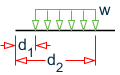
- Partial
- a moment which is constant in magnitude over a
portion of the member length
- Ends - a moment
that is applied at a set distance from each end of the member
|
| Direction
|
Select the direction in which the load acts.
- Global X
/ Y / Z – to apply loads parallel to the selected global axis.
- Local x /
y / z – to apply loads parallel to the selected local axis. Local x
loads are axial to a member.
-
Projected X / Y / Z – indicate the loads
along the projected length of the member in the corresponding global direction
|
| Uniform moment type
|
| Setting | Description |
|---|
| Magnitude
|
The magnitude of the
moment per unit length. Negative values may be used to reverse the direction.
|
|
| Partial moment type
|
| Setting | Description |
|---|
| Magnitude
|
The magnitude of the
moment per unit length. Negative values may be used to reverse the direction.
|
| As a percentage
|
Set this option to
specify the distance values as a fraction of the member length.
|
| Initial distance
|
The distance from the start node
to the beginning of the distributed moment.
|
| Final distance
|
The distance from the start node
to the end of the distributed moment.
|
|
| Ends moment type
|
| Setting | Description |
|---|
| As a percentage
|
The magnitude of the
moment per unit length. Negative values may be used to reverse the direction.
|
| Distance from the end
|
The distance of the loaded portion of
the member from each end.
|
|