To add a custom circular tank template
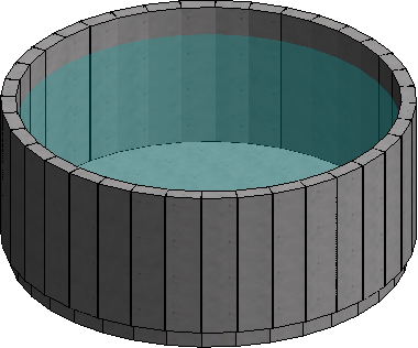
This tutorial demonstrates how to add a custom template to the Structure Wizard in STAAD.Pro Physical Modeler. In particular, this short template demonstrates how to create a circular water tank template.
-
Make a
copy of one of the existing two templates in the Structure Wizard and
rename it to
Circular Tank.
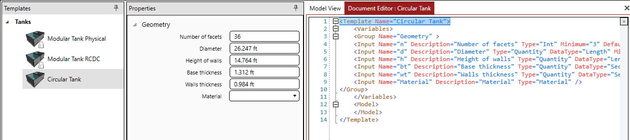
- Select the new template and then click the Edit Template tool in the File group in the ribbon tab. The XML contents of the template are displayed in a Document Editor tab.
- Select the full contents of the Document Editor and press <Delete>. You will be writing this template from scratch, but starting with an existing template is a good way to start any new XML template.
-
Type or paste the following framework elements within the XML
template:
<Template Name="Circular Tank"> <Variables> </Variables> <Model> </Model> </Template>Tip: XML is case-sensitive, so be careful to use the punctuation as noted in this example and in the XML schema documentation. - Click the Save tool in the File group on the ribbon tab. Notice that the Properties panel indicates the model contains errors. This is because there are no values for the template yet.
-
Within the
Variables element, add a new element
"Group"
with
"Input"
child elements which have attributes as follows:
<Group Name="Geometry" > <Input Name="n" Description="Number of facets" Type="Int" Minimum="3" Default="36" /> <Input Name="d" Description="Diameter" Type="Quantity" DataType="Length" Minimum="0 m" Default="8m" /> <Input Name="h" Description="Height of walls" Type="Quantity" DataType="Length" Minimum="0 m" Default="4.5 m" /> <Input Name="bt" Description="Base thickness" Type="Quantity" DataType="SectionDimension" Minimum="0 mm" Default="400 mm" /> <Input Name="wt" Description="Walls thickness" Type="Quantity" DataType="SectionDimension" Minimum="0 mm" Default="300 mm" /> <Input Name="Material" Description="Material" Type="Material" /> </Group>This adds user input parameters with the user-interface labels from the Description. Further, this provides value types, ranges, and default values for the fields.Note that the error message has disappeared and there are now several places for user input within a Geometry group. -
Within the Model element, add a new
"Loop"
element with a child element
"Node"
which have attributes as follows:
<!-- Nodes --> <Loop Variable="i" Start="0" End="n-1"> <Node ID="1+2*i" X="d/2*Cos(Radians(360/n*i))" Z="d/2*Sin(Radians(360/n*i))" /> <Node ID="2+2*i" X="d/2*Cos(Radians(360/n*i))" Y="h" Z="d/2*Sin(Radians(360/n*i))" /> </Loop>This adds a looping command which will generate nodes along the base and top of the tank outer wall.
-
Next, within the
Model element, add a
"Surface"
element containing a loop to generate a surface for the base and assign the
surface nodes to the surface ID:
<!-- Base --> <Surface ID="1" Thickness="bt" Material="Material" Attribute="SLAB_TANK" Alignment="Bottom"> <Loop Variable="i" Start="0" End="n-1"> <Node ID="1+2*i" /> </Loop> </Surface>Notice that this loop uses the same formula for the ID attribute as the node generation did in the previous step. This will then use the same node IDs for the base surface object.
-
Similarly, within the
Model element following the base generation
Surface, add a
Surface element within a
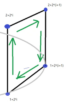
Loop in order to generate the wall around the tank:
<!-- Walls --> <Loop Variable="i" Start="0" End="n-1"> <Surface ID="i+2" Thickness="wt" Material="Material" Attribute="WALL_TANK"> <Node ID="1+2*i" /> <Node ID="2+2*i" /> <Node ID="2+2*((i+1)%n)" /> <Node ID="1+2*((i+1)%n)" /> </Surface> </Loop>This loops through each of the surface IDs (using a loop counter variable) and assigns the vertex node IDs to each corner based on the formulas demonstrated below:
-
Next add the supports.
This is done in a couple of sub-steps; one to capture the
user input and another to generate the
-
Within the
Input section, add a new
Group which contains the user input parameters
needed for the supports.
<Group Name="Supports" > <Input Name="allowTensile" Description="Allow tensile forces" Type="Bool" Default="false" /> <Input Name="soilMod" Description="Soil modulus" Type="Quantity" DataType="SubgradeModulus" Minimum="0 kN/m2/m" Default="80000 kN/m2/m" /> </Group>The use of the Group element becomes a bit more evident here once you save these changes, as a new category of template input appears. The "Bool" type of Input is used to create a check box option.
-
Next, following the
Surface elements within the
Model element, add the following code to
generate supports:
<!-- Base Support --> <Property Element="Surface" ID="1" Name="SupportDirection" Value="Y" /> <Property Element="Surface" ID="1" Name="MatSubgradeModulus" Value="soilMod" /> <If Condition="Not allowTensile"> <Then> <Property Element="Surface" ID="1" Name="MatAxialBehaviour" Value="CompressionOnly" /> </Then> </If>This assigns the support and soil modulus values to the Surface using multiple Property elements. The "If / Then" statement is used to assign a compression only attribute to the base surface if the user has selected to not allow for tensile force.
-
Within the
Input section, add a new
Group which contains the user input parameters
needed for the supports.
-
You will now add loads to the circular tank template.
Similar to supports, this takes multiple steps as the
template needs user input, to establish a load case, and then to generate the
hydrostatic load on the wall and base surfaces.
-
Within the
Input section, add a new
Group which contains the user input parameters
needed for the fluid density and height.
<Group Name="Loading" > <Input Name="fluidUW" Description="Fluid density" Type="Quantity" DataType="Density" Minimum="0 kg/m3" Default="1000 kg/m3" /> <Input Name="compFluidH" Description="Compartment fluid height" Type="Quantity" DataType="Length" Default="3.75 m" /> </Group> -
Next, following the support properties, add the following code
to specify the load case:
<!-- Load Case --> <LoadCase ID="1" Name="Fluid" Description="Fluid" Type="Staad_Fluids" />Tip: The load case attributes are all "hard coded" in this example in this "LoadCase" element's attributes, but you can also take user input for the Name and use that variable value here. -
Following the load case code, add the following code to
specify the hydrostatic loads on the surfaces:
<!-- Hydrostatic Load --> <Hydrostatic Y="compFluidH" Density="fluidUW" LoadConditionID="1"> <Polygon> <Loop Variable="i" Start="0" End="n-1"> <Point X="d/2*Cos(Radians(360/n*i))" Z="d/2*Sin(Radians(360/n*i))" /> </Loop> </Polygon> <Surface ID="1" /> <Loop Variable="i" Start="0" End="n-1"> <Surface ID="i+2" /> </Loop> </Hydrostatic>This section specifies the hydrostatic load in the load case using the user input values using a "Hydrostatic" element. Further, the "Polygon" elements generate the values to determine the shape of the loading pattern. Lastly, the surface IDs are specified, with the wall surfaces being specified within a Loop.
-
Within the
Input section, add a new
Group which contains the user input parameters
needed for the fluid density and height.
- Finally, save your template and then close the Document Editor tab.
Completed Code
The complete XML template is as follows:
<Template Name="Circular Tank">
	<Variables>
		<Group Name="Geometry" >
			<Input Name="n" Description="Number of facets" Type="Int" Minimum="3" Default="36" />
			<Input Name="d" Description="Diameter" Type="Quantity" DataType="Length" Minimum="0 m" Default="8m" />
			<Input Name="h" Description="Height of walls" Type="Quantity" DataType="Length" Minimum="0 m" Default="4.5 m" />
			<Input Name="bt" Description="Base thickness" Type="Quantity" DataType="SectionDimension" Minimum="0 mm" Default="400 mm" />
			<Input Name="wt" Description="Walls thickness" Type="Quantity" DataType="SectionDimension" Minimum="0 mm" Default="300 mm" />
			<Input Name="Material" Description="Material" Type="Material" />
		</Group>
		<Group Name="Supports" >
			<Input Name="allowTensile" Description="Allow tensile forces" Type="Bool" Default="false" />
			<Input Name="soilMod" Description="Soil modulus" Type="Quantity" DataType="SubgradeModulus" Minimum="0 kN/m2/m" Default="80000 kN/m2/m" />
		</Group>
		<Group Name="Loading" >
			<Input Name="fluidUW" Description="Fluid density" Type="Quantity" DataType="Density" Minimum="0 kg/m3" Default="1000 kg/m3" />
			<Input Name="compFluidH" Description="Compartment fluid height" Type="Quantity" DataType="Length" Default="3.75 m" />
		</Group>
	</Variables>
	<Model>

		<!-- Nodes -->
		<Loop Variable="i" Start="0" End="n-1">
			<Node ID="1+2*i" X="d/2*Cos(Radians(360/n*i))" Z="d/2*Sin(Radians(360/n*i))" />
			<Node ID="2+2*i" X="d/2*Cos(Radians(360/n*i))" Y="h" Z="d/2*Sin(Radians(360/n*i))" />
		</Loop>

		<!-- Base -->
		<Surface ID="1" Thickness="bt" Material="Material" Attribute="SLAB_TANK" Alignment="Bottom">
			<Loop Variable="i" Start="0" End="n-1">
				<Node ID="1+2*i" />
			</Loop>
		</Surface>

		<!-- Walls -->
		<Loop Variable="i" Start="0" End="n-1">
			<Surface ID="i+2" Thickness="wt" Material="Material" Attribute="WALL_TANK">
				<Node ID="1+2*i" />
				<Node ID="2+2*i" />
				<Node ID="2+2*((i+1)%n)" />
				<Node ID="1+2*((i+1)%n)" />
			</Surface>
		</Loop>

		<!-- Base Support -->
		<Property Element="Surface" ID="1" Name="SupportDirection" Value="Y" />
		<Property Element="Surface" ID="1" Name="MatSubgradeModulus" Value="soilMod" />
		<If Condition="Not allowTensile">
			<Then>
				<Property Element="Surface" ID="1" Name="MatAxialBehaviour" Value="CompressionOnly" />
			</Then>
		</If>

		<!-- Load Case -->
		<LoadCase ID="1" Name="Fluid" Description="Fluid" Type="Staad_Fluids" />

		<!-- Hydrostatic Load -->
		<Hydrostatic Y="compFluidH" Density="fluidUW" LoadConditionID="1">
			<Polygon>
				<Loop Variable="i" Start="0" End="n-1">
					<Point X="d/2*Cos(Radians(360/n*i))" Z="d/2*Sin(Radians(360/n*i))" />
				</Loop>
			</Polygon>
			<Surface ID="1" />
			<Loop Variable="i" Start="0" End="n-1">
				<Surface ID="i+2" />
			</Loop>
		</Hydrostatic>

	</Model>
</Template>