Modular Water Tank Tutorial
In this tutorial, you will use the Structure Wizard to parametrically create a modular water tank.
Create an Empty Physical Model
- In STAAD.Pro, select the New tab in the Start page.
- Type Modular Tank Tutorial in the File Name field.
- Select a convenient location to store the STAAD files.
- Select Physical as the Type.
- Select English as the Units.
- Type Modular Water Tank Tutorial in the Title field.
- Click Create. STAAD.Pro opens directly to the STAAD.Pro Physical Modeler.

Add Tank Geometry Data
-
On the
Model ribbon tab, select the
Structure Wizard tool in the
Create group.

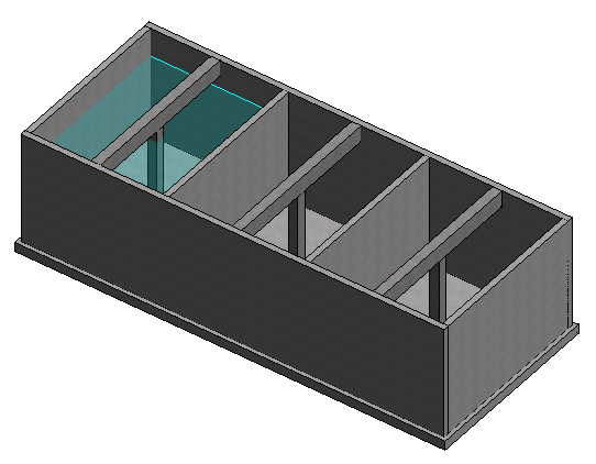
The STAAD.Pro Physical Modeller Structure Wizard window opens. - In the Geometry group, type 3 in the No of compartments.
- Type 16 in in the Base thickness field.
- Type 60 ft in the Total length field and then type 24 ft in the Total width field.
- Type 6 in in the Toe to edge of walls field.
- Type 16 ft in the Height of walls field.
- Type 10 in in both the Outer walls thickness and Separator walls thickness fields.
- Leave the Has columns option checked and use the default sizes for columns and beams.
- Leave the Material selected as Concrete (which it will be if this is the only material in the catalog).
- Leave the Include roof slab check box cleared.
Add Support and Load Data
- Clear the Pile below support check box and the Allow tensile forces check box if either are checked
- Select Soil in the Support foundation drop-down list.
- Type 650 (kip/ft2/ft) in the Soil modulus field.
- Select Load Case from the Load condition type drop-down list.
- Leave the Include self weight option checked and the Fluid density as the default of 0.0624 kip/ft3 (the density for water in English units).
- Click in the Compartment fluid height drop-down list. The list of fluid heights for each compartment is displayed in the pop-up table.
-
Type the following heights in this table:
ID Height (in.) 1 144 2 60 3 10 - Click OK.
Transfer the Tank Model Data
- Specify the reference point for the model. This will be where the tank model is inserted into the physical model from the Structure Wizard.
-
Select the
Transfer Template tool.

The Structure Wizard closes and the Insert Model dialog opens. - In this tutorial, leave the Insertion Point as the default (the WCS origin). You can specify a point in any coordinate system previously created if you have a need to locate the tank elsewhere.
- Click Preview. A dashed line version of the tank is temporarily shown in the model view. You can use the model navigation tools to update the view as needed to confirm the placement.
- Click OK. The model is added in a wireframe view with all fluid loads as area loads.

