To specify cross-section positioning
To select a different insertion point to realign the longitudinal axis on a predefined offset (i.e, member "hang points"), use the following procedure.
You can offset members with respect to
the local x-axis of the member with cross-section positioning. A series of predefined
points on a cross-section can be used to align with the analytical model line.
- Select the members which will all have the same member alignment.
-
On the Member ribbon tab, select the Cross Section Position tool.

The Modify Member Alignment dialog opens. -
Select the cross section position from the list.
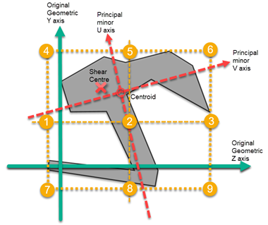
- Points 1 through 9:
these correspond to the center, corners, and mid-edges of a fictitious bounding
box around the shape's extreme most points along in the local coordinates.
- 1) Mid depth left
- 2) Mid depth center
- 3) Mid depth right
- 4) Top left
- 5) Top center
- 6) Top right
- 7) Bottom left
- 8) Bottom center
- 9) Bottom right
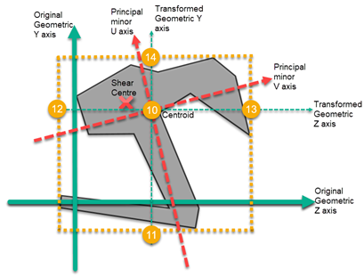
- Points 10 through
14: these correspond to the geometric center (i.e., centroid) of the shape and
the mid-edges of a bounding box containing the shape's extreme edges.
- 10) Geometric centroid (default)
- 11) Bottom in line with geometric centroid
- 12) Left in line with geometric centroid
- 13) Right in line with geometric centroid
- 14) Top in line with geometric centroid
- Points 1 through 9:
these correspond to the center, corners, and mid-edges of a fictitious bounding
box around the shape's extreme most points along in the local coordinates.
- Click OK. The dialog closes and the member centroids are translated away from the analytical centerline as selected.