EX. US-16 Time History Analysis for Forcing Function and Ground Motion
Dynamic Analysis (Time History) is performed for a 3 span beam with concentrated and distributed masses. The structure is subjected to "forcing function" and "ground motion" loading. The maxima of joint displacements, member end forces and support reactions are determined.
This problem is installed with the program by default to C:\Users\Public\Public Documents\STAAD.Pro 2023\Samples\Sample Models\US\US-16 Time History Analysis for Forcing Function and Ground Motion.STD when you install the program.
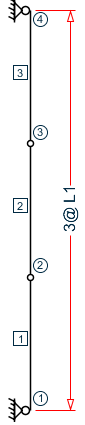
Where:
- L1 = 3.5 ft
STAAD PLANE EXAMPLE FOR TIME HISTORY ANALYSIS
Every input file has to start with the word STAAD. The term PLANE signifies that the structure is a plane frame.
UNITS FEET KIP
Specifies the units to be used.
    JOINT COORDINATES
    1  0.0   0.0   0.0
    2  0.0   3.5   0.0
    3  0.0   7.0   0.0
    4  0.0  10.5   0.0
Joint number followed by the X, Y and Z coordinates are specified above.
    MEMBER INCIDENCES
    1 1 2 3
Incidences of members 1 to 3 are specified above.
    UNIT INCH
    MEMBER PROPERTIES
    1 2 3 PRIS AX 3.0 IZ 240.0
All the members have PRISMATIC property specification. Since this is a plane frame, Area of cross section (AX) and Moment of Inertia (IZ) about the Z axis are adequate for the analysis.
    SUPPORTS
    1 4 PINNED
Pinned supports are located at nodes 1 and 4.
    DEFINE MATERIAL START
    ISOTROPIC CONCRETE
    E 14000
    POISSON 0.17
    DENSITY 8.7e-005
    ALPHA 5e-006
    DAMP 0.05
    G 1346.15
    TYPE CONCRETE
    STRENGTH FCU 4
    END DEFINE MATERIAL
    CONSTANTS
    MATERIAL CONCRETE ALL
The DEFINE MATERIAL command is used to specify material properties and the CONSTANT is used to assign the material to all members.
    DEFINE TIME HISTORY
    TYPE 1 FORCE
    0.0 -0.0001 0.5 0.0449 1.0 0.2244 1.5 0.2244 2.0 0.6731 2.5 -0.6731
    TYPE 2 ACCELERATION
    0.0 0.001 0.5 -7.721 1.0 -38.61 1.5 -38.61 2.0 -115.82 2.5 115.82
    ARRIVAL TIMES
    0.0
    DAMPING 0.075
There are two stages in the command specification required for a time history analysis. The first stage is defined above. First the characteristics of the time varying load are provided. The loading type may be a forcing function (vibrating machinery) or ground motion (earthquake). The former is input in the form of time-force pairs while the latter is in the form of time-acceleration pairs. Following this data, all possible arrival times for these loads on the structure as well as the modal damping ratio are specified. In this example, the damping ratio is the same (7.5%) for all modes.
    UNIT FEET
    LOAD 1 STATIC LOAD
    MEMBER LOAD
    1 2 3 UNI GX 0.5
Load case 1 above is a static load. A uniformly distributed force of 0.5 kip/ft acts along the global X direction on all 3 members.
    LOAD 2 TIME HISTORY LOAD
    SELFWEIGHT X 1.0
    SELFWEIGHT Y 1.0
    JOINT LOAD
    2 3 FX 2.5
    TIME LOAD
    2 3 FX 1 1
    GROUND MOTION X 2 1
This is the second stage in the command specification for time history analysis. This involves the application of the time varying load on the structure. The masses that constitute the mass matrix of the structure are specified through the selfweight and joint load commands. The program will extract the lumped masses from these weights. Following that, both the TIME LOAD and GROUND MOTION are applied simultaneously.
The Time load command is used to apply the Type 1 force, acting in the global X direction, at arrival time number 1, at nodes 2 and 3. The Ground motion, namely, the Type 2 time history loading, is also in the global X direction at arrival time 1.
PERFORM ANALYSIS
The above command initiates the analysis process.
    UNIT INCH
    PRINT JOINT DISPLACEMENTS
During the analysis, the program calculates joint displacements for every time step. The absolute maximum value of the displacement for every joint is then extracted from this joint displacement history. So, the value printed using the above command is the absolute maximum value for each of the six degrees of freedom at each node.
    UNIT FEET
    PRINT MEMBER FORCES
    PRINT SUPPORT REACTION
The member forces and support reactions too are calculated for every time step. For each degree of freedom, the maximum value of the member force and support reaction is extracted from these histories and reported in the output file using the above command.
FINISH
Input File
STAAD PLANE EXAMPLE FOR TIME HISTORY ANALYSIS
UNITS FEET KIP
JOINT COORDINATES
1  0.0   0.0  0.0
2  0.0   3.5  0.0
3  0.0   7.0  0.0
4  0.0  10.5  0.0
MEMBER INCIDENCES
1 1 2 3
UNIT INCH
MEMBER PROPERTIES
1 2 3 PRIS AX 3.0 IZ 240.0
SUPPORTS
1 4 PINNED
DEFINE MATERIAL START
ISOTROPIC CONCRETE
E 14000
POISSON 0.17
DENSITY 8.7e-005
ALPHA 5e-006
DAMP 0.05
G 1346.15
TYPE CONCRETE
STRENGTH FCU 4
END DEFINE MATERIAL
CONSTANTS
MATERIAL CONCRETE ALL
DEFINE TIME HISTORY
TYPE 1 FORCE
0.0 -0.0001 0.5 0.0449 1.0 0.2244 1.5 0.2244 2.0 0.6731 2.5 -0.6731
TYPE 2 ACCELERATION
0.0 0.001 0.5 -7.721 1.0 -38.61 1.5 -38.61 2.0 -115.82 2.5 115.82
ARRIVAL TIMES
0.0
DAMPING 0.075
UNIT FEET
LOAD 1 STATIC LOAD
MEMBER LOAD
1 2 3 UNI GX 0.5
LOAD 2 TIME HISTORY LOAD
SELFWEIGHT X 1.0
SELFWEIGHT Y 1.0
JOINT LOAD
2 3 FX 2.5
TIME LOAD
2 3 FX 1 1
GROUND MOTION X 2 1
PERFORM ANALYSIS
UNIT INCH
PRINT JOINT DISPLACEMENTS
UNIT FEET
PRINT MEMBER FORCES
PRINT SUPPORT REACTION
FINISHSTAAD Output File
                                                                  PAGE NO.    1
             ****************************************************
             *                                                  *
             *           STAAD.Pro 2023                         *
             *           Version  23.00.02.***                  *
             *           Proprietary Program of                 *
             *           Bentley Systems, Inc.                  *
             *           Date=    DEC 14, 2023                  *
             *           Time=     9:37:17                      *
             *                                                  *
             *  Licensed to: Bentley Systems Inc                *
             ****************************************************
     1. STAAD PLANE EXAMPLE FOR TIME HISTORY ANALYSIS
INPUT FILE: D:\Documentation\STAAD.Pro\_Automated_Py\output\2023-12-14\SPro_Output_Input_Files\Sample .. .STD
     2. UNITS FEET KIP
     3. JOINT COORDINATES
     4. 1  0.0   0.0  0.0
     5. 2  0.0   3.5  0.0
     6. 3  0.0   7.0  0.0
     7. 4  0.0  10.5  0.0
     8. MEMBER INCIDENCES
     9. 1 1 2 3
    10. UNIT INCH
    11. MEMBER PROPERTIES
    12. 1 2 3 PRIS AX 3.0 IZ 240.0
    13. SUPPORTS
    14. 1 4 PINNED
    15. DEFINE MATERIAL START
    16. ISOTROPIC CONCRETE
    17. E 14000
    18. POISSON 0.17
    19. DENSITY 8.7E-005
    20. ALPHA 5E-006
    21. DAMP 0.05
    22. G 1346.15
    23. TYPE CONCRETE
    24. STRENGTH FCU 4
    25. END DEFINE MATERIAL
    26. CONSTANTS
    27. MATERIAL CONCRETE ALL
    28. DEFINE TIME HISTORY
    29. TYPE 1 FORCE
    30. 0.0 -0.0001 0.5 0.0449 1.0 0.2244 1.5 0.2244 2.0 0.6731 2.5 -0.6731
    31. TYPE 2 ACCELERATION
    32. 0.0 0.001 0.5 -7.721 1.0 -38.61 1.5 -38.61 2.0 -115.82 2.5 115.82
    33. ARRIVAL TIMES
    34. 0.0
    35. DAMPING 0.075
    36. UNIT FEET
    37. LOAD 1 STATIC LOAD
    38. MEMBER LOAD
      EXAMPLE FOR TIME HISTORY ANALYSIS                        -- PAGE NO.    2
    39. 1 2 3 UNI GX 0.5
    40. LOAD 2 TIME HISTORY LOAD
    41. SELFWEIGHT X 1.0
    42. SELFWEIGHT Y 1.0
    43. JOINT LOAD
    44. 2 3 FX 2.5
    45. TIME LOAD
    46. 2 3 FX 1 1
    47. GROUND MOTION X 2 1
    48. PERFORM ANALYSIS
            P R O B L E M   S T A T I S T I C S
            -----------------------------------
     NUMBER OF JOINTS          4  NUMBER OF MEMBERS       3
     NUMBER OF PLATES          0  NUMBER OF SOLIDS        0
     NUMBER OF SURFACES        0  NUMBER OF SUPPORTS      2
           Using 64-bit analysis engine.
           SOLVER USED IS THE IN-CORE ADVANCED MATH SOLVER
   TOTAL      PRIMARY LOAD CASES =     2, TOTAL DEGREES OF FREEDOM =       8
   TOTAL LOAD COMBINATION  CASES =     0  SO FAR.
   ***NOTE: MASSES DEFINED UNDER LOAD#       2 WILL FORM
            THE FINAL MASS MATRIX FOR DYNAMIC ANALYSIS.
 MORE MODES WERE REQUESTED THAN THERE ARE FREE MASSES.
 NUMBER OF MODES REQUESTED              =     6
 NUMBER OF EXISTING MASSES IN THE MODEL =     4
 NUMBER OF MODES THAT WILL BE USED      =     4
   ***  EIGENSOLUTION : ADVANCED METHOD ***
      EXAMPLE FOR TIME HISTORY ANALYSIS                        -- PAGE NO.    3
               CALCULATED FREQUENCIES FOR LOAD CASE       2
       MODE            FREQUENCY(CYCLES/SEC)         PERIOD(SEC)
         1                      14.559                  0.06869
         2                      56.387                  0.01773
         3                     944.536                  0.00106
         4                    1635.985                  0.00061
            MODAL WEIGHT (MODAL MASS TIMES g) IN KIP          GENERALIZED
      MODE           X             Y             Z              WEIGHT
         1       5.021924E+00  0.000000E+00  0.000000E+00    5.021924E+00
         2       2.258180E-27  0.000000E+00  0.000000E+00    5.021924E+00
         3       0.000000E+00  2.192400E-02  0.000000E+00    2.192400E-02
         4       0.000000E+00  3.824466E-33  0.000000E+00    2.192400E-02
 MASS PARTICIPATION FACTORS
                     MASS  PARTICIPATION FACTORS IN PERCENT
                     --------------------------------------
           MODE    X     Y     Z     SUMM-X   SUMM-Y   SUMM-Z
             1   100.00   0.00   0.00  100.000    0.000    0.000
             2     0.00   0.00   0.00  100.000    0.000    0.000
             3     0.00 100.00   0.00  100.000  100.000    0.000
             4     0.00   0.00   0.00  100.000  100.000    0.000
    A C T U A L  MODAL  D A M P I N G  USED IN ANALYSIS
    MODE       DAMPING
       1      0.07500000
       2      0.07500000
       3      0.07500000
       4      0.07500000
   TIME STEP USED IN TIME HISTORY ANALYSIS = 0.00139 SECONDS
   NUMBER OF MODES WHOSE CONTRIBUTION IS CONSIDERED =    2
      EXAMPLE FOR TIME HISTORY ANALYSIS                        -- PAGE NO.    4
   WARNING-NUMBER OF MODES LIMITED TO A FREQUENCY OF   360.0 DUE TO THE DT VALUE ENTERED.
   TIME DURATION OF TIME HISTORY ANALYSIS =      2.500 SECONDS
   NUMBER OF TIME STEPS IN THE SOLUTION PROCESS =     1800
    49. UNIT INCH
  BASE SHEAR UNITS ARE -- KIP  FEET
  MAXIMUM BASE SHEAR  X=  -2.864840E+00  Y=   0.000000E+00  Z=   0.000000E+00
      AT TIMES               2.006944           0.000000           0.000000
    50. PRINT JOINT DISPLACEMENTS
  JOINT    DISPLACE
      EXAMPLE FOR TIME HISTORY ANALYSIS                        -- PAGE NO.    5
   JOINT DISPLACEMENT (INCH RADIANS)    STRUCTURE TYPE = PLANE
   ------------------
 JOINT  LOAD   X-TRANS   Y-TRANS   Z-TRANS   X-ROTAN   Y-ROTAN   Z-ROTAN
      1    1    0.00000   0.00000   0.00000   0.00000   0.00000  -0.00103
           2    0.00000   0.00000   0.00000   0.00000   0.00000  -0.00075
      2    1    0.03537   0.00000   0.00000   0.00000   0.00000  -0.00050
           2    0.02632   0.00000   0.00000   0.00000   0.00000  -0.00038
      3    1    0.03537   0.00000   0.00000   0.00000   0.00000   0.00050
           2    0.02632   0.00000   0.00000   0.00000   0.00000   0.00038
      4    1    0.00000   0.00000   0.00000   0.00000   0.00000   0.00103
           2    0.00000   0.00000   0.00000   0.00000   0.00000   0.00075
   ************** END OF LATEST ANALYSIS RESULT **************
    51. UNIT FEET
    52. PRINT MEMBER FORCES
  MEMBER   FORCES
      EXAMPLE FOR TIME HISTORY ANALYSIS                        -- PAGE NO.    6
   MEMBER END FORCES    STRUCTURE TYPE = PLANE
   -----------------
   ALL UNITS ARE -- KIP  FEET     (LOCAL )
  MEMBER  LOAD  JT     AXIAL   SHEAR-Y  SHEAR-Z   TORSION     MOM-Y      MOM-Z
      1    1     1      0.00      2.62     0.00      0.00      0.00      -0.00
                 2      0.00     -0.88     0.00      0.00      0.00       6.12
           2     1      0.00      1.43     0.00      0.00      0.00       0.00
                 2      0.00     -1.43     0.00      0.00      0.00       5.01
      2    1     2      0.00      0.88     0.00      0.00      0.00      -6.12
                 3      0.00      0.88     0.00      0.00      0.00       6.12
           2     2      0.00      0.00     0.00      0.00      0.00      -5.01
                 3      0.00      0.00     0.00      0.00      0.00       5.01
      3    1     3      0.00     -0.88     0.00      0.00      0.00      -6.12
                 4      0.00      2.62     0.00      0.00      0.00       0.00
           2     3      0.00     -1.43     0.00      0.00      0.00      -5.01
                 4      0.00      1.43     0.00      0.00      0.00       0.00
   ************** END OF LATEST ANALYSIS RESULT **************
    53. PRINT SUPPORT REACTION
  SUPPORT  REACTION
      EXAMPLE FOR TIME HISTORY ANALYSIS                        -- PAGE NO.    7
   SUPPORT REACTIONS -UNIT KIP  FEET    STRUCTURE TYPE = PLANE
   -----------------
 JOINT  LOAD   FORCE-X   FORCE-Y   FORCE-Z     MOM-X     MOM-Y     MOM Z
      1    1     -2.62      0.00      0.00      0.00      0.00      0.00
           2     -1.43      0.00      0.00      0.00      0.00      0.00
      4    1     -2.62      0.00      0.00      0.00      0.00      0.00
           2     -1.43      0.00      0.00      0.00      0.00      0.00
   ************** END OF LATEST ANALYSIS RESULT **************
    54. FINISH
             *********** END OF THE STAAD.Pro RUN ***********
               **** DATE= DEC 14,2023   TIME=  9:37:18 ****
      EXAMPLE FOR TIME HISTORY ANALYSIS                        -- PAGE NO.    8
         ************************************************************
         *   For technical assistance on STAAD.Pro, please visit    *
         *   http://www.bentley.com/en/support/                     *
         *                                                          *
         *   Details about additional assistance from               *
         *   Bentley and Partners can be found at program menu      *
         *   Help->Technical Support                                *
         *                                                          *
         *           Copyright (c) Bentley Systems, Inc.            *
         *                http://www.bentley.com                    *
         ************************************************************