EX. US-8 Concrete Design for a Space Frame
In this example, concrete design is performed on some members of a space frame structure. Design calculations consist of computation of reinforcement for beams and columns. Secondary moments on the columns are obtained through the means of a P-Delta analysis.
This problem is installed with the program by default to C:\Users\Public\Public Documents\STAAD.Pro 2023\Samples\Sample Models\US\US-8 Concrete Design for a Space Frame.STD when you install the program.
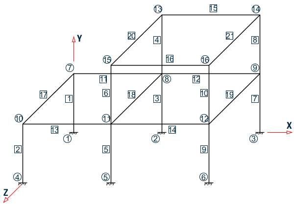
The above example represents a space frame, and the members are made of concrete. The input in the next page will show the dimensions of the members.
Two load cases, namely one for dead plus live load and another with dead, live and wind load, are considered in the design.
Actual input is shown in bold lettering followed by explanation.
STAAD SPACE FRAME WITH CONCRETE DESIGN
Every input has to start with the term STAAD. The word SPACE signifies that the structure is a space frame structure (3-D) and the geometry is defined through X, Y and Z coordinates.
UNIT KIP FT
Defines the input units for the data that follows.
    JOINT COORDINATE
    1 0 0 0 ; 2 18 0 0 ; 3 38 0. 0
    4 0 0 24 ; 5 18 0 24 ; 6 38 0 24
    7 0 12 0 ; 8 18 12 0 ; 9 38 12 0
    10 0 12 24 ; 11 18 12 24 ; 12 38 12 24
    13 18 24 0 ; 14 38 24 0 ; 15 18 24 24
Joint number followed by X, Y and Z coordinates are provided above.
    MEMBER INCIDENCE
    1 1 7 ; 2 4 10 ; 3 2 8 ; 4 8 13
    5 5 11 ; 6 11 15 ; 7 3 9 ; 8 9 14
    9 6 12 ; 10 12 16 ; 11 7 8 12
    13 10 11 14  ; 15 13 14 ; 16 15 16
    17 7 10 ; 18 8 11 ; 19 9 12
    20 13 15 ; 21 14 16
Defines the members by the joints to which they are connected.
    UNIT INCH
    MEMB PROP
    1  2  PRISMATIC YD  12.0  IZ  509. IY  509. IX  1018.
    3  TO  10 PR YD  12.0  ZD  12.0  IZ  864. IY  864. IX  1279.
    11  TO  21 PR YD  21.0  ZD  16.0  IZ  5788.  IY  2953.  IX  6497.
All member properties are provided using the PRISMATIC option. YD and ZD stand for depth and width. If ZD is not provided, a circular shape with diameter = YD is assumed for that cross section. All properties required for the analysis, such as, Area, Moments of Inertia, etc. are calculated automatically from these dimensions unless these are explicitly defined. For this particular example, moments of inertia (IZ, IY) and torsional constant (IX) are provided, so these will not be recalculated. The IX, IY, and IZ values provided in this example are only half the values of a full section to account for the fact that the full moments of inertia will not be effective due to cracking of concrete. Clause 10.11.1 of ACI 318-99 offers some guidelines on the amount of reduction to be applied on the gross section moment of inertia for beams, columns, walls and slabs to account for cracking.
    DEFINE MATERIAL START
    ISOTROPIC CONCRETE
    E 3150
    POISSON 0.17
    DENSITY 8.7e-005
    ALPHA 5e-006
    DAMP 0.05
    G 1346.15
    TYPE CONCRETE
    STRENGTH FCU 4
    END DEFINE MATERIAL
    CONSTANTS
    MATERIAL CONCRETE ALL
    UNIT FT
The DEFINE MATERIAL command is used to define material properties for concrete. The CONSTANT command is used to assign this to all members.
    SUPPORT
    1 TO 6 FIXED
Joints 1 to 6 are fixed supports.
LOAD 1 (1.4DL + 1.7LL)
Load case 1 is initiated followed by a title.
SELF Y -1.4
The selfweight of the structure is applied in the global Y direction with a -1.4 factor. Since global Y is vertically upward, the negative factor indicates that this load will act downwards.
    MEMB LOAD
    11  TO  16  UNI  Y  -2.8
    11  TO  16  UNI  Y  -5.1
Load 1 contains member loads also. Y indicates that the load is in the local Y direction. The word UNI stands for uniformly distributed load.
LOAD 2 .75 (1.4DL + 1.7LL + 1.7WL)
Load case 2 is initiated followed by a title.
    REPEAT LOAD
    1 0.75
The preceding command will gather the load data values from load case 1, multiply them with a factor of 0.75 and utilize the resulting values in load 2.
    JOINT LOAD
    15  16  FZ  8.5
    11  FZ  20.0
    12  FZ  16.0
    10  FZ  8.5
Load 2 contains some additional joint loads also. FZ indicates that the load is a force in the global Z direction.
PDELTA ANALYSIS
This command instructs the program to proceed with the analysis. The analysis type is P-DELTA indicating that second-order effects are to be calculated.
PRINT FORCES LIST 2 5 9 14 16
Member end forces are printed using the above PRINT commands. The LIST option restricts the print output to the members listed.
START CONCRETE DESIGN
The above command initiates a concrete design.
    CODE ACI
    TRACK 1.0 MEMB 14
    TRACK 2.0 MEMB 16
    MAXMAIN 11 ALL
The values for the concrete design parameters are defined in the above commands. Design is performed per the ACI 318 Code. The TRACK value dictates the extent of design related information that should appear in the output. MAXMAIN indicates that the maximum size of main reinforcement is the #11 bar. These parameters are described in the manual where American concrete design related information is available.
DESIGN BEAM 14 16
The above command instructs the program to design beams 14 and 16 for flexure, shear, and torsion.
DESIGN COLUMN 2 5
The above command instructs the program to design columns 2 and 5 for axial load and biaxial bending.
END CONCRETE DESIGN
This will end the concrete design.
FINISH
This command terminates the STAAD run.
Input File
STAAD SPACE FRAME WITH CONCRETE DESIGN
UNIT KIP FT
JOINT COORDINATE
1 0 0 0 ; 2 18 0 0 ; 3 38 0. 0
4 0 0 24 ; 5 18 0 24 ; 6 38 0 24
7 0 12 0 ; 8 18 12 0 ; 9 38 12 0
10 0 12 24 ; 11 18 12 24 ; 12 38 12 24
13 18 24 0 ; 14 38 24 0 ; 15 18 24 24
16 38 24 24
MEMBER INCIDENCE
1 1 7 ; 2 4 10 ; 3 2 8 ; 4 8 13
5 5 11 ; 6 11 15 ; 7 3 9 ; 8 9 14
9 6 12 ; 10 12 16 ; 11 7 8 12
13 10 11 14 ; 15 13 14 ; 16 15 16
17 7 10 ; 18 8 11 ; 19 9 12
20 13 15 ; 21 14 16
UNIT INCH
MEMB PROP
1 2 PRISMATIC YD 12.0 IZ 509. IY 509. IX 1018.
3 TO 10 PR YD 12.0 ZD 12.0 IZ 864. IY 864. IX 1279.
11 TO 21 PR YD 21.0 ZD 16.0 IZ 5788. IY 2953. IX 6497.
DEFINE MATERIAL START
ISOTROPIC CONCRETE
E 3150
POISSON 0.17
DENSITY 8.7e-005
ALPHA 5e-006
DAMP 0.05
G 1346.15
TYPE CONCRETE
STRENGTH FCU 4
END DEFINE MATERIAL
CONSTANTS
MATERIAL CONCRETE ALL
UNIT FT
SUPPORT
1 TO 6 FIXED
LOAD 1 (1.4DL + 1.7LL)
SELF Y -1.4
MEMB LOAD
11 TO 16 UNI Y -2.8
11 TO 16 UNI Y -5.1
LOAD 2 .75(1.4DL + 1.7LL + 1.7WL)
REPEAT LOAD
1 0.75
JOINT LOAD
15 16 FZ 8.5
11 FZ 20.0
12 FZ 16.0
10 FZ 8.5
PDELTA ANALYSIS
PRINT FORCES LIST 2 5 9 14 16
START CONCRETE DESIGN
CODE ACI
TRACK 1.0 MEMB 14
TRACK 2.0 MEMB 16
MAXMAIN 11 ALL
DESIGN BEAM 14 16
DESIGN COLUMN 2 5
END CONCRETE DESIGN
FINISHSTAAD Output File
                                                                  PAGE NO.    1
             ****************************************************
             *                                                  *
             *           STAAD.Pro 2023                         *
             *           Version  23.00.02.***                  *
             *           Proprietary Program of                 *
             *           Bentley Systems, Inc.                  *
             *           Date=    DEC 14, 2023                  *
             *           Time=     9:38:45                      *
             *                                                  *
             *  Licensed to: Bentley Systems Inc                *
             ****************************************************
     1. STAAD SPACE FRAME WITH CONCRETE DESIGN
INPUT FILE: D:\Documentation\STAAD.Pro\_Automated_Py\output\2023-12-14\SPro_Output_Input_Files\Sample .. .STD
     2. UNIT KIP FT
     3. JOINT COORDINATE
     4. 1 0 0 0 ; 2 18 0 0 ; 3 38 0. 0
     5. 4 0 0 24 ; 5 18 0 24 ; 6 38 0 24
     6. 7 0 12 0 ; 8 18 12 0 ; 9 38 12 0
     7. 10 0 12 24 ; 11 18 12 24 ; 12 38 12 24
     8. 13 18 24 0 ; 14 38 24 0 ; 15 18 24 24
     9. 16 38 24 24
    10. MEMBER INCIDENCE
    11. 1 1 7 ; 2 4 10 ; 3 2 8 ; 4 8 13
    12. 5 5 11 ; 6 11 15 ; 7 3 9 ; 8 9 14
    13. 9 6 12 ; 10 12 16 ; 11 7 8 12
    14. 13 10 11 14 ; 15 13 14 ; 16 15 16
    15. 17 7 10 ; 18 8 11 ; 19 9 12
    16. 20 13 15 ; 21 14 16
    17. UNIT INCH
    18. MEMB PROP
    19. 1 2 PRISMATIC YD 12.0 IZ 509. IY 509. IX 1018.
    20. 3 TO 10 PR YD 12.0 ZD 12.0 IZ 864. IY 864. IX 1279.
    21. 11 TO 21 PR YD 21.0 ZD 16.0 IZ 5788. IY 2953. IX 6497.
    22. DEFINE MATERIAL START
    23. ISOTROPIC CONCRETE
    24. E 3150
    25. POISSON 0.17
    26. DENSITY 8.7E-005
    27. ALPHA 5E-006
    28. DAMP 0.05
    29. G 1346.15
    30. TYPE CONCRETE
    31. STRENGTH FCU 4
    32. END DEFINE MATERIAL
    33. CONSTANTS
    34. MATERIAL CONCRETE ALL
    35. UNIT FT
    36. SUPPORT
    37. 1 TO 6 FIXED
    38. LOAD 1 (1.4DL + 1.7LL)
      FRAME WITH CONCRETE DESIGN                               -- PAGE NO.    2
    39. SELF Y -1.4
    40. MEMB LOAD
    41. 11 TO 16 UNI Y -2.8
    42. 11 TO 16 UNI Y -5.1
    43. LOAD 2 .75(1.4DL + 1.7LL + 1.7WL)
    44. REPEAT LOAD
    45. 1 0.75
    46. JOINT LOAD
    47. 15 16 FZ 8.5
    48. 11 FZ 20.0
    49. 12 FZ 16.0
    50. 10 FZ 8.5
    51. PDELTA ANALYSIS
            P R O B L E M   S T A T I S T I C S
            -----------------------------------
     NUMBER OF JOINTS         16  NUMBER OF MEMBERS      21
     NUMBER OF PLATES          0  NUMBER OF SOLIDS        0
     NUMBER OF SURFACES        0  NUMBER OF SUPPORTS      6
           Using 64-bit analysis engine.
           SOLVER USED IS THE IN-CORE ADVANCED MATH SOLVER
   TOTAL      PRIMARY LOAD CASES =     2, TOTAL DEGREES OF FREEDOM =      60
   TOTAL LOAD COMBINATION  CASES =     0  SO FAR.
   ++ Adjusting Displacements.
    52. PRINT FORCES LIST 2 5 9 14 16
  FORCES   LIST     2        5
      FRAME WITH CONCRETE DESIGN                               -- PAGE NO.    3
   MEMBER END FORCES    STRUCTURE TYPE = SPACE
   -----------------
   ALL UNITS ARE -- KIP  FEET     (LOCAL )
  MEMBER  LOAD  JT     AXIAL   SHEAR-Y  SHEAR-Z   TORSION     MOM-Y      MOM-Z
      2    1     4     68.01     -4.02    -0.69      0.00      2.85     -17.70
                10    -66.03      4.02     0.69     -0.00      5.48     -30.94
           2     4     54.80     -3.35    -6.58      1.03     41.93     -15.37
                10    -53.31      3.35     6.58     -1.03     41.50     -25.37
      5    1     5    289.52     -0.45    -0.72      0.00      3.08      -4.21
                11   -286.99      0.45     0.72     -0.00      5.54      -3.04
           2     5    227.65     -0.88   -12.16      0.90     88.74      -6.81
                11   -225.76      0.88    12.16     -0.90     82.17      -5.84
      9    1     6    170.70      4.47    -0.67     -0.00      2.79      16.47
                12   -168.18     -4.47     0.67      0.00      5.27      36.05
           2     6    139.15      2.84   -13.36      0.17     92.01       8.79
                12   -137.26     -2.84    13.36     -0.17     84.24      24.01
     14    1    11     -9.12     97.25     0.00     -0.23     -0.01     371.86
                12      9.12     70.57    -0.00      0.23     -0.00    -104.95
           2    11     -7.75     73.11     0.64     -0.87     -8.77     280.25
                12      7.75     52.76    -0.64      0.87     -3.99     -76.74
     16    1    15     13.58     84.52    -0.00      0.03     -0.00     104.14
                16    -13.58     83.30     0.00     -0.03      0.00     -91.95
           2    15     10.19     63.36     0.07     -0.08     -0.79      78.03
                16    -10.19     62.50    -0.07      0.08     -0.59     -69.48
   ************** END OF LATEST ANALYSIS RESULT **************
    53. START CONCRETE DESIGN
 CONCRETE DESIGN
    54. CODE ACI
    55. TRACK 1.0 MEMB 14
    56. TRACK 2.0 MEMB 16
    57. MAXMAIN 11 ALL
    58. DESIGN BEAM 14 16
      FRAME WITH CONCRETE DESIGN                               -- PAGE NO.    4
      FRAME WITH CONCRETE DESIGN                               -- PAGE NO.    5
                       STAAD.PRO CONCRETE DESIGN - (ACI-318-14)   v2.0
                       ***********************************************
Units: KIP   , FEET   (Unless Noted Otherwise)
 Member :     14
DESIGN SUMMARY
-----------------------------------------------------------------------------
| Status         :   Pass         Type    : Beam            Length:   20.000 |
| Critical Ratio :   1.000        Criteria: Shear Y                          |
| Critical Clause:   9.5.3/9.5.4                                             |
-----------------------------------------------------------------------------
CROSS SECTION
-------------------------------------------------------
| Shape: Rectangular | Width:    1.33 | Depth:    1.75 |
-------------------------------------------------------
LONGITUDINAL BAR LAYOUT
---------------------------------------------------------------------------
|                |    Bars     |      Location     | Distance  |   Anchor  |
|       Position | Nums | Size | Start  |   End    | From Face | Start End |
---------------------------------------------------------------------------
|         Bottom |    3 | # 6  |    0.00|    20.00 |     0.16  |  Yes  Yes |
|         Bottom |    3 | # 6  |    4.52|    18.65 |     0.16  |   No   No |
|            Top |    3 | #10  |    0.00|    20.00 |     0.18  |  Yes  Yes |
|            Top |    2 | #10  |    0.00|     7.16 |     0.18  |  Yes   No |
---------------------------------------------------------------------------
TRANSVERSE BAR LAYOUT
------------------------------------------------------------------------------------
|                                |        Asv        |     Rebar Specification      |
| Zone | Dir.|  From   |    To   |  Reqd.  |  Prov.  | Nums | Size | Spacing | Legs |
------------------------------------------------------------------------------------
|    1 |  Y  |    0.00 |    5.00 |  0.0097 |  0.0122 |   23 |  # 4 |   0.23  |   2  |
|    1 |  Z  |    0.00 |    5.00 |  0.0097 |  0.0122 |   23 |  # 4 |   0.23  |   2  |
|    2 |  Y  |    5.00 |   20.00 |  0.0071 |  0.0081 |   45 |  # 4 |   0.34  |   2  |
|    2 |  Z  |    5.00 |   20.00 |  0.0071 |  0.0081 |   45 |  # 4 |   0.34  |   2  |
------------------------------------------------------------------------------------
------------------------ Member:    14 Design Ends ------------------------
      FRAME WITH CONCRETE DESIGN                               -- PAGE NO.    6
                       STAAD.PRO CONCRETE DESIGN - (ACI-318-14)   v2.0
                       ***********************************************
Units: KIP   , FEET   (Unless Noted Otherwise)
 Member :     16
DESIGN SUMMARY
-----------------------------------------------------------------------------
| Status         :   Pass         Type    : Beam            Length:   20.000 |
| Critical Ratio :   0.943        Criteria: Flexure                          |
| Critical Clause:   9.5.2                                                   |
-----------------------------------------------------------------------------
CROSS SECTION
-------------------------------------------------------
| Shape: Rectangular | Width:    1.33 | Depth:    1.75 |
-------------------------------------------------------
DESIGN INPUTS
-------------------------------------------------------------------------
| Concrete | Fc         576.000 |                     | Ec     0.519E+06 |
| Steel    | Fy(main)  8639.999 | Fy(trans)  8639.999 | Es     0.418E+07 |
| Cover    | Top          0.125 | Bottom        0.125 | Sides      0.125 |
-------------------------------------------------------------------------
Design Messages
-------------------------------------------------------------------------
   WARNINGS: DESIGN FOR MEMBER    16
   ---------------------------------
    1) Review shear min density/max spacing Cl 9.7.6.2.2
CRITICAL STRENGTH RESULTS
-----------------------------------------------------------------------
| Category |    Demand     |  Min Capacity  |  Max Capacity  |  Ratio  |
-----------------------------------------------------------------------
| Axial    |        -13.584|       -699.120 |        192.780 |   0.019 |
| Flexure  |       -104.139|       -110.383 |        199.179 |   0.943 |
| Shear Y  |         84.523|       -127.636 |        127.636 |   0.662 |
| Shear Z  |         -0.073|        -28.307 |         28.307 |   0.003 |
| Torsion  |          0.000|          0.000 |          0.000 |   0.000 |
-----------------------------------------------------------------------
LONGITUDINAL BAR DETAILS AT CROSS SECTIONS
---------------------------------------------------------------------------------
| Distance | Position |  Ast-reqd  |  Ast-prov  | No(s)bars| Size | No of Layers |
---------------------------------------------------------------------------------
|    0.000 |     Top  |      0.008 |      0.008 |     6    |  # 4 |       1      |
|          |  Bottom  |      0.010 |      0.016 |     3    |  # 8 |       1      |
|    5.000 |     Top  |      0.003 |      0.008 |     6    |  # 4 |       1      |
|          |  Bottom  |      0.018 |      0.033 |     6    |  # 8 |       1      |
|   10.000 |     Top  |      0.003 |      0.008 |     6    |  # 4 |       1      |
|          |  Bottom  |      0.030 |      0.033 |     6    |  # 8 |       1      |
|   15.000 |     Top  |      0.003 |      0.008 |     6    |  # 4 |       1      |
|          |  Bottom  |      0.019 |      0.033 |     6    |  # 8 |       1      |
|   20.000 |     Top  |      0.007 |      0.008 |     6    |  # 4 |       1      |
|          |  Bottom  |      0.010 |      0.016 |     3    |  # 8 |       1      |
---------------------------------------------------------------------------------
      FRAME WITH CONCRETE DESIGN                               -- PAGE NO.    7
LONGITUDINAL BAR LAYOUT
---------------------------------------------------------------------------
|                |    Bars     |      Location     | Distance  |   Anchor  |
|       Position | Nums | Size | Start  |   End    | From Face | Start End |
---------------------------------------------------------------------------
|         Bottom |    3 | # 8  |    0.00|    20.00 |     0.17  |  Yes  Yes |
|         Bottom |    3 | # 8  |    2.27|    17.83 |     0.17  |   No   No |
|            Top |    6 | # 4  |    0.00|    20.00 |     0.15  |  Yes  Yes |
---------------------------------------------------------------------------
TRANSVERSE BAR LAYOUT
------------------------------------------------------------------------------------
|                                |        Asv        |     Rebar Specification      |
| Zone | Dir.|  From   |    To   |  Reqd.  |  Prov.  | Nums | Size | Spacing | Legs |
------------------------------------------------------------------------------------
|    1 |  Y  |    0.00 |   10.00 |  0.0093 |  0.0108 |   40 |  # 4 |   0.26  |   2  |
|    1 |  Z  |    0.00 |   10.00 |  0.0093 |  0.0108 |   40 |  # 4 |   0.26  |   2  |
|    2 |  Y  |   10.00 |   15.00 |  0.0053 |  0.0056 |   11 |  # 4 |   0.50  |   2  |
|    2 |  Z  |   10.00 |   15.00 |  0.0053 |  0.0056 |   11 |  # 4 |   0.50  |   2  |
|    3 |  Y  |   15.00 |   20.00 |  0.0092 |  0.0106 |   20 |  # 4 |   0.26  |   2  |
|    3 |  Z  |   15.00 |   20.00 |  0.0092 |  0.0106 |   20 |  # 4 |   0.26  |   2  |
------------------------------------------------------------------------------------
------------------------ Member:    16 Design Ends ------------------------
    59. DESIGN COLUMN 2 5
      FRAME WITH CONCRETE DESIGN                               -- PAGE NO.    8
      FRAME WITH CONCRETE DESIGN                               -- PAGE NO.    9
                       STAAD.PRO CONCRETE DESIGN - (ACI-318-14)   v2.0
                       ***********************************************
Units: KIP   , FEET   (Unless Noted Otherwise)
  |--------------------------------------------------------------------|
  |   Member :      2                                                    |
  |  Type   : Column           Shape  : Circular                       |
  |--------------------------------------------------------------------|
  |  AREA OF STEEL REQUIRED                                            |
  |--------------------------------------------------------------------|
  |  Section -       |    1    |    2    |    3    |    4    |    5    |
  |--------------------------------------------------------------------|
  |  Location        |    0.00 |    3.00 |    6.00 |    9.00 |   12.00 |
  |  As(Longitudinal)|    0.02 |    0.01 |    0.01 |    0.01 |    0.02 |
  |  As/sv(Trans Y)  |    0.00 |    0.00 |    0.00 |    0.00 |    0.00 |
  |  As/sv(Trans Z)  |    0.00 |    0.00 |    0.00 |    0.00 |    0.00 |
  |--------------------------------------------------------------------|
  |--------------------------------------------------------------------|
  |   Member :      5                                                    |
  |  Type   : Column           Shape  : Rectangular                    |
  |--------------------------------------------------------------------|
  |  AREA OF STEEL REQUIRED                                            |
  |--------------------------------------------------------------------|
  |  Section -       |    1    |    2    |    3    |    4    |    5    |
  |--------------------------------------------------------------------|
  |  Location        |    0.00 |    3.00 |    6.00 |    9.00 |   12.00 |
  |  As(Longitudinal)|    0.06 |    0.02 |    0.01 |    0.01 |    0.05 |
  |  As/sv(Trans Y)  |    0.00 |    0.00 |    0.00 |    0.00 |    0.00 |
  |  As/sv(Trans Z)  |    0.00 |    0.00 |    0.00 |    0.00 |    0.00 |
  |--------------------------------------------------------------------|
    60. END CONCRETE DESIGN
    61. FINISH
             *********** END OF THE STAAD.Pro RUN ***********
               **** DATE= DEC 14,2023   TIME=  9:38:48 ****
      FRAME WITH CONCRETE DESIGN                               -- PAGE NO.   10
         ************************************************************
         *   For technical assistance on STAAD.Pro, please visit    *
         *   http://www.bentley.com/en/support/                     *
         *                                                          *
         *   Details about additional assistance from               *
         *   Bentley and Partners can be found at program menu      *
         *   Help->Technical Support                                *
         *                                                          *
         *           Copyright (c) Bentley Systems, Inc.            *
         *                http://www.bentley.com                    *
         ************************************************************