TR.31.2.11 IS:1893 (Part 1) 2016 Codes - Lateral Seismic Load
This feature enables one to generate seismic loads per the IS:1893 specifications using a static equivalent approach per Part 1 (2016) for building structures.
The seismic load generator can be used to generate lateral loads in the X and Z directions only. Y is the direction of gravity loads. This facility has not been developed for cases where the Z axis is set to be the vertical direction (See the SET Z UP command in TR.5 Set Command Specification).
General Format
DEFINE IS1893 2016 ( ACCIDENTAL ) LOAD
1893-2016-spec
wall-definitions
Refer to Wall Area Definitions for information on defining walls.
weight-data
Refer to Common Weight Data for information on how to specify structure weight for seismic loads.
where
1893-2016-spec = ZONE f1 RF f2 I f3 { SS f4 | SA f11 } (ST f5) ( { DM f6 | DF f12 } ) (PX f7) (PZ f8) ( { DT f9 | GL f10 } ) (HT f13) (DX f14) (DZ f15)
Notes
-
If the ACCIDENTAL option is specified, the accidental torsion will be calculated per the IS 1893 specifications. The value of the accidental torsion is based on the center of mass for each level. The center of mass is calculated from the SELFWEIGHT, JOINT WEIGHT, and MEMBER WEIGHT commands you have specified.
The ACC option along with accidental eccentricity factor (generally 0.05 as per IS 1893 code) needs to be provided in the 1893 seismic primary load case (i.e., 1893 LOAD X / Z f1 ACC f3 ). f2 can be negative. See TR.32.12.2 Generation of Seismic Loads
To consider horizontal torsion in cases where a floor diaphragm is present in the model, the ACCIDENTAL option should not be specified. Instead, dynamic eccentricity along with accidental eccentricity should be provided in the 1893 seismic primary load case (i.e., 1893 LOAD X / Z f1 DEC f2 ACC f3 ). For equivalent seismic analysis, f2 is 1.5 and f3 is 0.05 as per IS 1893 code. f1 is always positive or zero, however f2 can be negative. If f2 is 0.0, only accidental torsion will be considered for this particular load case.
-
By default, STAAD.Pro calculates natural periods of the structure in both X and Z directions respectively which are used in calculation for base shear. If PX and PZ are included, the program will consider these values for calculation of average response acceleration coefficient. If ST is used instead of PX and PZ values, then the program will calculate natural period depending upon the empirical expression given in IS: 1893 (Part 1)-2016.
-
In the case where no rigid floor diaphragm is present, STAAD.Pro identifies columns and shear walls (without openings) as vertical components for the purpose of computing lateral stiffness of the story.
The lateral stiffness of a column is calculated as:
where12EI / L3 - E
= - Young's modulus
- I
= - moment of inertia
- L
= - length of the column
The lateral stiffness for a shear wall (without opening) is calculated as:
Which is the summation of inverse of flexural stiffness and inverse of shear stiffness, obtained as deflection of a cantilever wall under a single lateral load, P, at its top.
where- h
= - height
- A
= - cross-sectional area
- G
= - shear modulus of the wall
The summation of lateral stiffnesses of all columns and shear walls at a particular floor level constitutes the total lateral stiffness of that particular story or floor level. The program checks for a soft story of a building along both global X and Z directions respectively. This computation is valid only for those structures whose floors are treated as rigid diaphragm
-
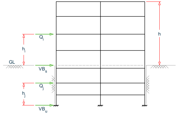
Clause 6.4.5 of IS:1893 part-I -2016 stipulates that for underground structures and foundation at a depth 30m or below, the design horizontal spectrum (Ah or Ak) value should be taken as half of the actual one for structures placed between ground level and 30 m depth the design horizontal acceleration spectrum must be interpolated between Ah and (0.5 Ah). The reduction of Ah should be done on the potion of the structure (mass situated below GL) located below ground.
You can provide DT or GL parameter to tell the program what your actual depth of foundation below the ground level.
The program will then evaluate the multiplication factor on Ah and calculate the base shear. This reduces the actual base shear for underground portion and the base shear, VB is distributed into story shear of that portion (for static analysis).
- For the portion of the
structure above the ground, the design lateral force at the ith
floor, Qi:
where
- Wi
= - seismic weight of ith floor above the ground
- hi
= - height of ith floor above the ground
- VBs
= - horizontal base shear = Ah·Ws
- Ws
= - seismic weight of the portion which is above the ground
- For the portion of the
structure below the ground, the design lateral force at the jth
floor, Qj:
where
- Wj
= - seismic weight of jth floor below the ground
- hj
= - height of jth floor below the ground
- VBu
= - horizontal base shear = AhR·Wu
- Wu
= - seismic weight of the portion which is below the ground
- For the portion of the
structure above the ground, the design lateral force at the ith
floor, Qi:
where
Example
DEFINE IS1893 2016 LOAD
ZONE 0.36 RF 5 I 1.2 SS 1 ST 1 DM 0.05
JOINT WEIGHT
39 60 80 WEIGHT 100
LOAD 1 LOADTYPE Seismic  TITLE SS_(+X)
1893 LOAD X 1
LOAD 2 LOADTYPE Seismic  TITLE SS_(+Z)
1893 LOAD Z 1
LOAD 3 LOADTYPE Seismic  TITLE SS_(+Y)
1893 LOAD Y 1
Methodology
The design base shear is computed by STAAD.Pro for building structures as per IS: 1893 (Part 1) 2016:
| V = Ah.W |
| = | ||
| = |
- You provide seismic zone coefficient and desired 1893 specs through the DEFINE 1893 LOAD command.
- The program calculates the structure period, T.
- The program calculates Sa/g utilizing T. For the Y direction, Sa/g = 2.5 per clause 6.4.6.
- The program calculates V from the above equation. W is obtained from mass table data entered via SELFWEIGHT, JOINT WEIGHT(s), MEMBER WEIGHT(S), and/or REFERENCE LOAD you provide through the DEFINE 1893 LOAD command.
- The total lateral seismic load (base shear) is then distributed by the program among different levels of the structure per the IS: 1893 procedures.
See TR.32.12 Generation of Loads for additional information.
IS 1893 2016 Implementation
- 7.2.2 - A minimum of lateral base shear which needs to be distributed to each floor (or each node of each floor) in a building is calculated per Table 7 and Clause 7.2.2. This is used to determine a minimum base shear value.
- 7.2.3 - An additional importance factor has been added.
- 7.2.4 - 5% damping should be used for all structures, regardless of the material. The program will accept other values in the DM parameter, but a warning will be issued in the output.
- 7.2.6 - The user interface includes a list of response reduction factors taken from Table 10 of IS 1893 2016.
- 7.6.2 - Calculation of
the approximate time-period based on height of the building
- For point a, the time period is calculated as follows for reinforced-concrete and steel composite MRF builds: Ta = 0.080.75.
- For point b and point c, the time period is a function of the wall area. Therefore, the wall-data-pairs must provided to correctly calculate the time period for ST 4 or 5 (reinfroced concrete structural walls or all "other" buildings).