TR.31.2.6 Chinese Static Seismic per GB50011-2010
General Format
The following general format should be used to generate loads in a particular direction.
DEFINE GB50011 ( 2010 ) (ACCIDENTAL) LOAD
INTENSITY s1 { FREQUENT | FORTIFIED | RARE } GROUP i1 SCLASS i2 (DAMP f1) GFACTOR { 0.85 | 1.0 } (DELN f2) (SF f3) (PX f4) (PZ f5)
Where:
Generation of GB50011 Seismic Load
To apply the load in any load case, following command would be used
LOAD CASE i
GB LOAD { X | Y | Z } (f6) (ACC f7)
Where:
| Parameter | Description |
|---|---|
| LOAD i | load case number |
| GB LOAD { X | Y | Z } f6 | An optional factor to multiply horizontal seismic load. |
| ACC f7 | The multiplying factor for Accidental Torsion, to be used to multiply the accidental torsion load (default = 1.0). May be negative (otherwise, the default sign for MY is used based on the direction of the generated lateral forces). |
Gravity Loads for Design
In the computation of seismic action, the representative value of gravity load of the building shall be taken as the sum of characteristic values of the weight of the structure and members plus the combination values of variable loads on the structure. The combination coefficients for different variable loads shall be taken from the following table.
| Type of Variable | land Combination coefficient | |
|---|---|---|
| Snow load | 0.5 | |
| Dust load on roof | 0.5 | |
| Live load on roof | Not considering | |
| Live load on the floor, calculated according to actual state | 1.0 | |
| Live load on the floor, calculated according to equivalent uniform state | Library, archives | 0.8 |
| Other civil buildings | 0.5 | |
| Gravity for hanging object of crane | Hard hooks | 0.3 |
| Soft hooks | Not considering | |
Seismic Influence Coefficient
This shall be determined for building structures according to the Intensity, Site-class, Design seismic group, and natural period and damping ratio of the structure. The maximum value of horizontal seismic influence coefficient shall be taken from Table 5.1.4-1; the characteristic period shall be taken from Table 5.1.4-2 according to Site-class and Design seismic group, that shall be increased 0.05s for rarely earthquake.
| Earthquake influence | Intensity 6 | Intensity 7 | Intensity 8 | Intensity 9 |
|---|---|---|---|---|
| Frequent earthquake | 0.04 | 0.08 (0.12) | 0.16(0.24) | 0.32 |
| Fortified earthquake (per clause 3.10.3) |
0.12 | 0.23 (0.34) | 0.45 (0.68) | 0.90 |
| Rarely earthquake | 0.28 | 0.50(0.72) | 0.90(1.20) | 1.40 |
| Earthquake Group | Site class | ||||
|---|---|---|---|---|---|
| I0 | I | II | III | IV | |
| 1 | 0.20 | 0.25 | 0.35 | 0.45 | 0.65 |
| 2 | 0.25 | 0.30 | 0.40 | 0.55 | 0.75 |
| 3 | 0.30 | 0.35 | 0.45 | 0.65 | 0.90 |
Calculation of Seismic Influence Coefficient
The design base shear is computed in accordance with the equations shown below.
The damping adjusting and forming parameters on the building seismic influence coefficient curve (Fig.2.1) shall comply with the following requirements:
-
The damping ratio of building structures shall select 0.05 except otherwise provided, the damping adjusting coefficient of the seismic influence coefficient curve shall select 1.0, and the coefficient of shape shall conform to the following provisions:
- Linear increase section, whose period (T) is less than 0.1 s;
- Horizontal section, whose period form 0. is thought to characteristic period, shall select the maximum value (αmax);
- Curvilinear decrease section, whose period from characteristic period thought to 5 times of the characteristic period, the power index (γ) shall choose 0.9.
- Linear decrease section, whose period from 5 times characteristic period thought to 6s, the adjusting factor of slope (η1) shall choose 0.02.
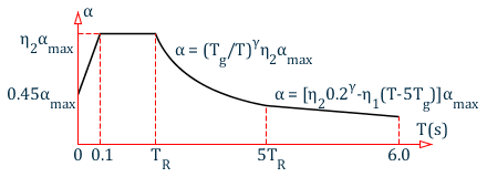
Seismic influence coefficient curve
-
When the damping adjusting and forming parameters on the seismic influence coefficient curve shall comply with the following requirements:
-
The power index of the curvilinear decreased section shall be determined according to the following equation:
where- γ
= - the power index of the curvilinear decrease section
- ξ
= - the damping ratio
-
The adjusting factor of slope for the linear decrease section shall be determined from following equation:
where- η1
= - the adjusting factor of slope for the linear decrease section, when it is less than 0, shall equal 0.
-
The damping adjustment factor shall be determined according to the following equation:
where- η2
= - the damping adjustment factor, when it is smaller than 0.55 shall equal 0.55.
-
Calculation of Horizontal Seismic Action
Characteristic Value of Horizontal Seismic Action
When the base shear force method is used, only one degree of freedom may be considered for each story; the characteristic value of horizontal seismic action of the structure shall be determined by the following equations:
| E2.4 |
| E2.5 |
| E2.6 |
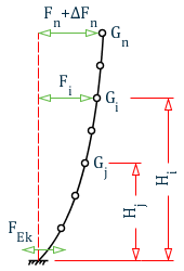
Calculation of horizontal seismic action
| = | ||
| = | ||
| = | ||
| = | ||
| = | ||
| = | ||
| = | ||
| = |
| Tg (s) | T1 > 1.4Tg | T1 ≤ 1.4Tg |
| Tg ≤ 0.35 | 0.08T1 + 0.07 | 0 |
| 0.35 < Tg ≤ 0.55 | 0.08T1 + 0.01 | |
| Tg > 0.55 | 0.08T1 − 0.02 |
Horizontal Seismic Shear Force Verification
The horizontal seismic shear force at each floor level of the structure shall comply with the requirement of the following equation:
| E2.7 |
| = | ||
| = | ||
| = |
| Structures | Intensity 6 | Intensity 7 | Intensity 8 | Intensity 9 |
|---|---|---|---|---|
| structures with obvious torsion effect or fundamental period is less than 3.5s | 0.008 | 0.16 (0.024) | 0.032 (0.048) | 0.064 |
| Structures with fundamental period greater than 5.0s | 0.006 | 0.012 (0.018) | 0.024 (0.032) | 0.040 |