V. GB500017-2017 Single Angle section with Axial Force
Verify the slenderness, strength, and stability of a single-angle section subject to axial force per GB50017-2017.
Reference
MOHURD. 2017. GB 50017-2017 Standard for design of steel structures . Beijing, China: Ministry of Housing and Urban-Rural Development
Problem
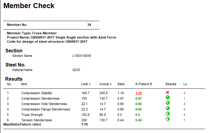
The section is an L100x100x6 with a length of 3.005 m. The structure is a truss model. Member #34 assigned with single angle section (L100x100x6) is designed per GB 50017-2017. The governing load combination (#4) is 1.2 DL + 1.4 LL and the ultimate force on the member, N, is 92.06 kN of axial compression.
The material is Q235 type steel.
- Design strength in tension, compression, and flexure: fy = 215 MPa
- Design strength in shear: fv = 125 MPa
Calculations
Section Properties
- Side length, b = h = 100 mm
- Thickness, t = 6 mm
- Cross-sectional area, A = 1,193 mm2
- Moment of inertia about x, Ix = 479,000 mm4
- Moment of inertia about y, Iy = 1,820,000 mm4
- Radius of gyration about x, ix = 20.04 mm
- Radius of gyration about y, iy = 39.06 mm
- Area moment about x, Sx = 15,890 mm3
- Area moment about y, Sx = 31,690 mm3
Slenderness Ratio
According to Table 7.4.1-1 of GB50017-2017, effective length of double angle is:
lox = μx×lx = 0.8 × 3,005 mm = 2,404 mm
loy =μy×ly = 1.0 ×3,005 mm = 3,005 mm
According to formula 7.2.1-1 and 2 of steel structures code, slenderness ratio of double angle with X axis and Y axis is:
According to formula 7.2.2-3 and 7.2.2.-4 of steel structures code, torsional buckling equivalent slenderness ratio of single angle is calculated as follows.
The relative coordinates from the centroid to the heel (corner) of the angle are:
xc = 27.23 mm
yc = 27.23 mm
The distance from the centroid to the shear center, ys:
The polar radius of gyration of the shear center, i0:
Polar moment of inertia of gross angle to the shear center, I0:
The free torsion constant of shear center on gross angle section. The correction factor for the free torsion factor, k = 1.2.
Fan moment of inertia of the gross angle section to shear center, Iω:
Length for torsional buckling, lω = 2,404 mm. The torsional buckling equivalent slenderness ratio, λz2:
Calculate the slenderness ratio for flexural torsional buckling, λyz:
The maximum slenderness ratio of the single angle section,
The limit of slenderness ratio of compression member is 150 according to table 7.4.6 of steel structures code.
The limit of slenderness ratio of tension member is 300 according to table 7.4.7 of steel structures code.
Tension or Compression Strength
According to Table 7.1.3 of GB50017-2017, the η = 0.85.
According to formula 7.1.1-1 of steel structures code, the stress of single angle with gross cross-section area is:
According to clause 7.6.1-1 of steel structures code, reduction factor of strength design value of angle is 0.85.
And the ratio is:
According to formula 7.1.1-2 of the steel structures code, the strength ratio is:
And the ratio is:
Steel Grade Correction Factor
The steel type is Q235. According to note 1 in table 3.5.1 of Standard for design of steel structures and table 1 of Standard for design of steel structures. Commentary 2.2, the steel grade correction coefficient is εk = 1.
Compressive Strength
According to table 7.2.1-1 of steel structures code, the double angle section class is b.
The slenderness ratio of double angle on X axis, . So,
Class b, so, the coefficients are α1 = 0.650, α2 = 0.965, and α3 = 0.300.
Since , then the stability factor in x:
The slenderness ratio of double angle on symmetry axis is . So,
Class b, so, the coefficients are α1 = 0.650, α2 = 0.965, and α3 = 0.300.
Since , then the stability factor in xy:
The minimum stability factor is 0.384.
Compression Flange Width to Thickness Ratio
From GB50017-2017 Clause 7.3.1-5, when λ = 80εk, the formula 7.3.1-7 should be used to obtain the value of the width to thickness of a compression member. Here, λyz = 130.7 and εk = 1.
So, the limiting value of the width to thickness ratio = 5εk + 0.125λ = 5 + 0.125 × 130.7 = 21.34.
According to Clause 7.3.2 of GB50017-2017,
ϕA×f = 0.384 × 1,193 × 215 = 98,494
N = 92,061 < ϕA×f , so the magnification factor
Therefore, Limit value of width to thickness ratio should be 1.034 × 21.34 = 22.07.
The width per formula 7.3.1-7 of GB50017-2017, w = b -2t = 100 - 2 × 6 = 88 mm.
The actual width to thickness ratio is
So the ratio is .
Since the section is a equal leg angle, the check for the height to thickness ratio is the same; therefore ok.
Stability of Compression Member
According to formula 7.6.1-2 of GB50017-2017,
η = 0.6 + 0.0015λ = 0.6 + 0.0015 × 130.7 = 0.796
The reduction factor of stability bearing capacity, ρe must be calculated as .
The member capacity according to formula 7.6.1-1 of GB50017-2017:
ρeηϕAf = 0.986 × 0.796 × 0.384 × 1,193 × 215 × 10-3 = 77.30 kN
So the ratio is ; Failed.
Comparison
| Result Type | Reference | STAAD.Pro | Difference | Comment |
|---|---|---|---|---|
| Compression Slenderness | 0.87 | 0.87 | none | |
| Tension Slenderness | 0.44 | 0.44 | none | |
| Truss Strength | 0.50 | 0.50 | none | |
| Compression Flange Slenderness | 0.66 | 0.66 | none | |
| Compression Web Slenderness | 0.66 | 0.66 | none | |
| Compression Stability | 1.19 | 1.19 | none |
STAAD.Pro Input File
The file C:\Users\Public\Public Documents\STAAD.Pro 2023\Samples \Verification Models\09 Steel Design\China\GB500017-2017 Single Angle section with Axial Force.std is typically installed with the program.
STAAD SPACE
START JOB INFORMATION
ENGINEER DATE 11-Aug-18
END JOB INFORMATION
INPUT WIDTH 79
UNIT METER KN
JOINT COORDINATES
1 0 0 0; 2 1.66667 0 0; 3 3.33333 0 0; 4 5 0 0; 5 6.66667 0 0; 6 8.33333 0 0;
7 10 0 0; 8 1.66667 2.5 0; 9 3.33333 2.5 0; 10 5 2.5 0; 11 6.66667 2.5 0;
12 8.33333 2.5 0; 13 0 0 2; 14 1.66667 0 2; 15 3.33333 0 2; 16 5 0 2;
17 6.66667 0 2; 18 8.33333 0 2; 19 10 0 2; 20 1.66667 2.5 2; 21 3.33333 2.5 2;
22 5 2.5 2; 23 6.66667 2.5 2; 24 8.33333 2.5 2;
MEMBER INCIDENCES
1 1 2; 2 2 3; 3 3 4; 4 4 5; 5 5 6; 6 6 7; 7 8 9; 8 9 10; 9 10 11; 10 11 12;
11 1 8; 12 8 3; 13 3 10; 14 10 5; 15 5 12; 16 12 7; 17 2 8; 18 4 10; 19 6 12;
20 3 9; 21 5 11; 22 13 14; 23 14 15; 24 15 16; 25 16 17; 26 17 18; 27 18 19;
28 20 21; 29 21 22; 30 22 23; 31 23 24; 32 13 20; 33 20 15; 34 15 22; 35 22 17;
36 17 24; 37 24 19; 38 14 20; 39 16 22; 40 18 24; 41 15 21; 42 17 23; 43 1 13;
44 2 14; 45 3 15; 46 4 16; 47 5 17; 48 6 18; 49 7 19; 50 8 20; 51 9 21;
52 10 22; 53 11 23; 54 12 24;
DEFINE MATERIAL START
ISOTROPIC STEEL
E 2.05e+008
POISSON 0.3
DENSITY 76.8195
ALPHA 1.2e-005
DAMP 0.03
TYPE STEEL
STRENGTH FY 253200 FU 407800 RY 1.5 RT 1.2
END DEFINE MATERIAL
MEMBER PROPERTY CHINESE
1 TO 10 22 TO 31 43 TO 54 TABLE ST PIP152X8.0
12 15 17 TO 21 33 36 38 TO 42 TABLE ST L80X80X6
11 16 32 37 TABLE SD L100X100X7
13 14 34 35 TABLE ST L100X100X6
CONSTANTS
MATERIAL STEEL ALL
MEMBER TRUSS
11 TO 21 32 TO 42
SUPPORTS
1 7 13 19 PINNED
LOAD 1 LOADTYPE None  TITLE DL
JOINT LOAD
2 TO 6 8 TO 12 14 TO 18 20 TO 24 FY -20
8 TO 12 20 TO 24 FY -40
LOAD 2 LOADTYPE None  TITLE LL
JOINT LOAD
8 TO 12 20 TO 24 FY -30
LOAD COMB 3 F : 1.20DL
1 1.2
LOAD COMB 4 F : 1.20DL+1.40LL
1 1.2 2 1.4
LOAD COMB 5 F : 1.00DL
1 1.0
LOAD COMB 6 F : 1.00DL+1.40LL
1 1.0 2 1.4
LOAD COMB 7 F : 1.20DL+0.98LL
1 1.2 2 0.98
LOAD COMB 8 F : 1.00DL+0.98LL
1 1.0 2 0.98
LOAD COMB 9 F : 1.35DL
1 1.35
LOAD COMB 10 F : 1.35DL+0.98LL
1 1.35 2 0.98
PERFORM ANALYSIS
FINISH
Chinese steel design parameters (.gsp file):
[version=2207]
*{ The below data is for code check general information, please do not modify it.
[CodeCheck]
SeismicGrade=None
BeamBendingStrength=1
BeamShearStrength=1
BeamEquivalentStress=1
BeamOverallStability=1
BeamSlendernessWeb=1
BeamSlendernessFlange=1
TrussStrength=1
TrussStability=1
TrussShearStrength=1
ColumnStrength=1
ColumnStabilityMzMy=1
ColumnStabilityMyMz=1
PressedTrussSlenderness=1
TensionTrussSlenderness=1
ColumnSlendernessFlange=1
ColumnSlendernessWeb=1
BeamDeflection=1
SelectAll=0
GroupOptimize=0
FastOptimize=0
Iteration=0
SecondaryMembers=
SectCollectionOrder=0
[CheckOptionAngle]
PrimaryAxis=60.000000
SecondaryAxis=60.000000
ExtendLine=10.000000
*{ The above data is for code check general information, please do not modify it.

[GROUP=1]
Name(Parameter Name)=TRUSS WEB MEMBER
Type(Member Type)=2
Principle(Principle Rules)=0
SteelNo()=Q235
SectionSlendernessRatioGrade(Section Slenderness Ratio Grade)=3
Fatigue(Fatigue Calculation)=0
Optimization(Perform optimized design)=0
MaxFailure(Failure Ratio)=1
MinTooSafe(Safety Ratio)=0.3
CheckLoadCase(Force Loads Case No.)=ALL
CheckDispLoadCase(Displacement Loads Case No.)=ALL
BeamBendingStrength()=1
BeamShearStrength()=1
BeamEquivalentStress()=1
BeamOverallStability()=1
BeamSlendernessFlange(b/t on beam)=1
BeamSlendernessWeb(h0/tw on beam)=1
TrussStrength(Axial Force Strength)=1
SecondaryMoment(Secondary Moment of Truss)=0
TrussStability(Solid-web Axial Compression Stability)=1
TrussShearStrength(Axial Shear Strength)=1
PressedTrussSlenderness(Pressed Member Slenderness)=1
TensionTrussSlenderness(Tension Member Slenderness)=1
ColumnStrength(Column Member Strength)=1
ColumnStabilityMzMy(Column Stability In-plane)=1
ColumnStabilityMyMz(Column Stability Out-plane)=1
ColumnSlendernessFlange(b/t on column)=1
ColumnSlendernessWeb(h0/tw on column)=1
CheckItemAPPENDIX_B11(Beam Deflection)=1
UseAntiSeismic(Use Seismic Adjusting Factor)=0
GamaReStr(Seismic Adjusting Factor of Load-bearing Capacity for Strength)=0
GamaReSta(Seismic Adjusting Factor of Load-bearing Capacity for Stability)=0
SLevel(Grade of Seismic Resistance)=0
lmdc(Slenderness Limit of Compression Member)=0
lmdt(Slenderness Limit of Tension Member)=0
Lmd831(Slenderness of Seismic Column)=0
Lmd841(Slenderness of Seismic Brace)=0
Lmd9213(Slenderness of Seismic Single-story Plant)=0
LmdH28(Slenderness of Seismic Multi-story Plant)=0
rz(Plastic Development Factor in Major Axis)=0
ry(Plastic Development Factor in Minor Axis)=0
gamaSharp(Plastic Development Factor of sharp side)=0
betamz(the equivalent moment factor in Major Axis plane)=0
betamy(the equivalent moment factor in Minor Axis plane)=0
betatz(the equivalent moment factor out Major Axis plane)=0
betaty(the equivalent moment factor out Minor Axis plane)=0
HasHorLoadZ(Has Horizontal Load in Z-Axis)=0
HasHorLoadY(Has Horizontal Load in Y-Axis)=0
DFF(Deflection Limit of Beam)=400
DJ1(Start Node Number in Major Axis)=0
DJ2(End Node Number in Major Axis)=0
Horizontal(Check for Deflection in Minor Axis)=0
Cantilever(Cantilever Member)=0
fabz(Overall Stability Factor in Major Axis of Bending Member)=0
faby(Overall Stability Factor in Minor Axis of Bending Member)=0
StressFeature(Select the Stress Feature to calulate stability factor of beam)=1
faz(Overall Stability Factor in Major Axis of Axial Compression Member=0
fay(Overall Stability Factor in Minor Axis of Axial Compression Member)=0
lz(Unbraced Length in Major Axis)=0
ly(Unbraced Length in Minor Axis)=0
miuz(Effective Length Factor for Column in Major Axis)=0.8
miuy(Effective Length Factor for Column in Minor Axis)=1
Lateral(Member in Frame Without Sidesway or not)=1
APZ(Gyration Radius Calculation as Z-Axis Parallel Leg)=0
rFlange(Limit Ratio of Width to Thickness for Flange)=0
rWeb(Limit Ratio of High to Thickness for Web)=0
BucklingStrength(Axis forced member bulking strength)=0
ZSectType(Section Type in Z-Axis)=0
YSectType(Section Type in Y-Axis)=0
HSectWebInTrussPlane(Web of H in Truss Plane)=0
rAn(Net Factor of Section Area)=1
rWnz(Net Factor of Resistance Moment in Z-Axis)=1
rWny(Net Factor of Resistance Moment in Y-Axis)=1
CapReduce(Seismic Reduction Factor of Load-bearing Capacity for Brace)=1
AngleReduce(Angle Strength Reduce)=1
LAglConSta(Connect Type of unequal single angle)=0
LAngleStrength(Reduction Factor of Angle Strength)=0
LAngleStability(Reduction Factor of Angle Stability)=0
rTrussSectReduce(Effective Factor of Axial Force Section)=0.85
Members(Member Number)=34