D12.A.6.1 Double symmetric wide flange profile
The von Mises stress is checked at four stress points as shown in figure below.
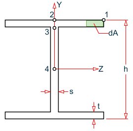
Stress points checked for a wide flange section
Section Properties
- Ax , Ix , Iy, and Iz are taken from STAAD.Pro database
- Ay = h × s Applied in STAAD.Pro print option PRINT MEMBER STRESSES
Az = (2/3)· b · t · 2
τy = Fy/Ay
τz = Fz/Az
- Ay and Az are not used in the code check
- ref. NS app. C3
Ty = dA × z
Tz = dA × y
Stress calculation
General stresses are calculated as:
Where the component stresses are calculated as shown in the following table:
| Point No | σx | σby | σbz | τx | τy | τz |
|---|---|---|---|---|---|---|
| 1 | 0 | 0 | ||||
| 2 | 0 | |||||
| 3 | 0 | 0 | ||||
| 4 | 0 | 0 | 0 |
In general wide flange profiles are not suitable for large torsional moments. The reported torsional stresses are indicative only. For members with major torsional stresses a separate evaluation has to be carried out. Actual torsional stress distribution is largely dependent on surface curvature at stress point and warping resistance.