M. To apply a wind load
To apply a defined wind load to your structure, use the following procedure.
-
Either:
The Add New Load Items dialog opens.
On the Loading ribbon tab, select the Load Items tool in the Loading Specifications group
 Tip: This will add the load item to the currently selected load group selected in the program status bar.
or
In the Load & Definition dialog, select a primary load case in the Load Cases Details list and then click Add.
-
Select the
tab.
Note: If you have not previously added a wind load definition to the model, this tab is inactive. Refer to M. To add a wind load definition for details.
- In the Select Type drop-down list, select the wind load definition for this load case.
-
Select the
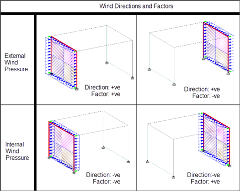
Direction of the load and then type the load
Factor value.
- X (External)
- Y (External) - for Z Up
- Z (External) - for Y Up (default)
- -X (Internal)
- -Y (Internal) - for Z Up
- -Z (Internal) - for Y Up (default
The direction options are dependant upon the global orientation of the model. The selected Direction and sign of the Factor affect how the wind is applied (i.e., "internal" or "external" pressure for an enclosed structure).
- (Optional) If the wind load definition is for a SNiP code, specify the additional SNiP Parameters:
-
Specify the range of values over which the load applies. Type the
along the global axis of how the wind load acts.
Depending on the arrangement of walls, you may need to sub-divide the wind load application into multiple entries with overlapping ranges. The program may not automatically recognize all open-ended wind panels. Refer to Controlling Open-Ended Panel Identification for additional details.
- (Optional) Check the Open Structure option for truss, lattice, or other open structure types. This will apply the load only to the projected area of the members and joints, not to the bounded area of members or surfaces.
- Click Add.