EX. To design the box section
-
On the
Specification ribbon tab, select the
tool in the
Beam Profiles group.

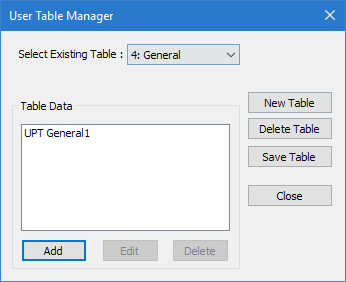
If no User Defined Table exists, you will be prompted to create one.
The User Table Manager dialog opens. - Click New Table. The New User Table dialog opens.
-
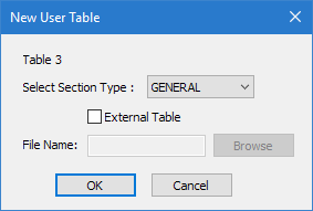
Specify the new external table:
- In the Select Section Type list, select GENERAL.
- Check the External Table option.
- Click Browse.
- Navigate to and select the file Bsection.upt exported from Section Wizard and then click OK.
- In the User Table Manager dialog, click Close.
-
Either:
The STAAD Analysis and Design dialog opens.
During the analysis (and design, if specified), an output file is generated. This file may contain selected input data items, results and error messages. Optional print specifications can be used to include additional information in the output file.
- Click Done.
-
Select Chinese Steel Design in the
Workflows panel.

-
On the Chinese Steel Design ribbon tab, select the
General Section tool in the Settings group.

The General Section dialog opens. -
Select the table row for BOX1 and then
enter the section values as follows:
Field Value Flange Width between 2 Webs 0.972 m Thickness of Flange (TF) 0.024 m Height of Web (BW) 1.552 m Thickness of Web (TW) 0.014 m 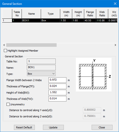
- Click Close.
-
On the Chinese Steel Design ribbon tab,
select the Design tool in the
Design group.

The Chinese Steel Design dialog opens. - Click Design. The design progress is displayed.
- Click Done.