D5.A.5.6 Design of Slender pipe sections to EN 1993-1-6
The design of Slender CHS sections is performed per EN 1993-1-6:2007 (hereafter, EC3-6). EC3-6 does not specify additional or modified safety factors. Therefore, the program uses the default safety factors from EN 1993-1-1.
EC3-6 deals with four types of ultimate limits states: plastic limit state, cyclic capacity limit state, buckling limit state, and fatigue. The following are considered by STAAD.Pro:
- LS1 – Plastic limit state: Deals with the condition when the capacity of the structure is exhausted by yielding of the material.
- LS3 – Buckling Limit state: Deals with the condition in which the structure (or shell) develops large displacements normal to the shell surface, caused by loss of stability under compressive and/or shear membrane stresses.
The limit state verification is made based on the Stress design method described in EC3-6. The stress design approach takes into account three categories of stresses:
- Primary stresses: Stresses that are generated for the member to be in equilibrium with the direct imposed loads.
- Secondary stresses: Those that are generated for internal compatibility or for compatibility at supports due to imposed loads or displacements (e.g., temperature, settlement etc.)
- Local stresses: Local stresses generated due to cyclic loading (or fatigue).
Only the primary stresses are considered the program. The primary stresses considered are those generated due to axial loads, bending, shear and /or a combination of these conditions.
The local axis coordinate system for a CHS is defined as:
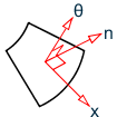
and the corresponding membrane stresses will follow the convention given below:
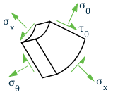
Nomenclature for membrane and transverse stresses in Slender CHS sections
D5.A.5.6.1 Stress Design
Stress checks are made based on the Stress design method as per Section 8.5 of the code. This section deals with the buckling strength of the member (LS3). The principle is to evaluate the membrane stresses due to the applied loads and then compare that to the buckling strength, which is evaluated giving due consideration for local buckling effects.
The membrane stresses are evaluated as given in Annex A of the code. The pipe section is considered as an unstiffened cylindrical shell.
-
Meridional Stresses:
-
Axial load
Fx = 2·π·r·Px
σx = -Fx/(2·π·r·t)
-
Axial stress from bending
M = π·r2·Px,max
σx = ±M/(π2·r·t)
-
-
Shear Stress:
-
Transverse force, V
V = π·r·Pθ,max
τmax = ±V/(π·r·t)
-
Shear from torsional moment, M
Mt = 2π·r2·Pθ
τ = Mt/(2π2·r2·t)
-
Where:
- r is the radius of the middle surface of the shell wall.
- t is the wall thickness of the cylinder
D5.A.5.6.2 Calculation of Axial Buckling Stress
The buckling strength of A slender pipe section is evaluated using the method given in section 8.5.2 ofEC3-6. The design buckling stresses (buckling resistance) are calculated separately for axial, circumferential, and shear. The circumferential stresses are ignored in STAAD.Pro.
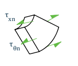
The naming convention and the coordinate axis used will be as given in the following diagram:
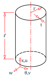
Naming convention and coordinate system used for the buckling stress of a slender CSH section
The axial buckling resistance is given by:
σx,Rd = σx,Rk/γM1
σx,Rk is the characteristic buckling strength given by:
| σx,Rk = Χx· fyk |
Once the relative slenderness is evaluated, the reduction factor is calculated as follows:
- χ = 1 when
- when
- when
| = |
The meridional buckling parameters the factors α and β are evaluated per section D.1.2.2 of EC3-6.
The elastic critical buckling stress, σx,cr and the factors α and β are evaluated per Annex D of EC3-6. The details are as given below:
The CHS section is classified based on the following criteria:
| CHS Length Classification | Criteria |
|---|---|
| Short | ω ≤ 1.7 |
| Medium | 1.7 < ω ≤ 0.5· r/t |
| Long | ω > 0.5· r/t |
Where:
The elastic critical buckling critical stress is evaluated as:
| σx,Rcr = 0.605·E·Cx·(t/r) |
| = |
|
D5.A.5.6.3 Calculation of Shear Buckling Stress
The shear buckling resistance is given by:
τxθ,Rd = τxθ,Rk/γM1
τxθ,Rk is the characteristic buckling shear strength given by:
| τxθ,Rk = Χθ· fyk |
The reduction factor, χθ, is then evaluated as described for the axial buckling stress, based on the same λ p, α, and β parameters given in Annex D of EC3-6.
The CHS section is classified based on the following criteria:
| CHS Length Classification | Criteria |
|---|---|
| Short | ω ≤ 10 |
| Medium | 10 < ω ≤ 8.7· r/t |
| Long | ω > 8.7· r/t |
Where:
The elastic critical buckling critical stress is evaluated as:
where| = |
|
D5.A.5.6.4 Buckling Strength Verification
The buckling strength verification will be performed so as to satisfy the following conditions:
For axial stresses:
σx,Ed ≤ σx,Rd
For shear stresses:
τxθ,Ed ≤ τxθ,Rd
For a combined case of axial and shear stresses acting together, an interaction check will be done according to equation 8.19 of the code as below:
where| = | kx = 1.25 + 0.75 · χx kτ = 1.75 + 0.25 · χτ |