To assign plate offsets
To add rigid link offsets to one or more corners of a plate, use the following procedure.
Plate corner
offsets can be used to model any situation where the corners of a plate element
do not coincide with the analytical node used for the plate incidences. For
example,
- walls that meet at a corner (e.g., so that walls do not overlap)
- wall and slab intersections (e.g., a wall that bears on top of a slab)
- (Optional) Select the plates which will have the same plate offset specifications assigned.
- Either: The Plate Specs dialog opens to the Offset tab.
-
Select the
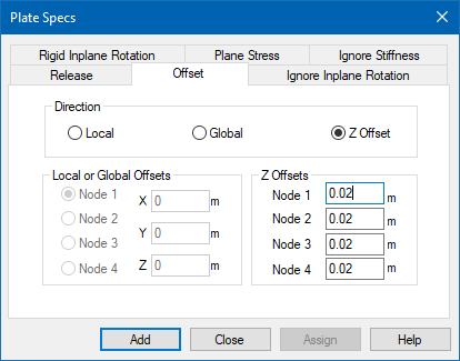
Direction in which you want to specify
offsets:
- Local - the nodal offsets at a specified joint are given in the element local axes.
- Global - the nodal offsets at a specified joint are given in the global axes.
- Z Offset - the offset is specified along the local z axis of the element (i.e., parallel offset to the plane of the element)
-
Specify the offset values:
For… Do… Local or global offsets Select the local incidence node number and then specify the offsets in the local or global directions. Z offsets Type the offset value to use. By default, the same value will populate in all the node fields (i.e., a parallel offset to the plane of the plate). You can override these values by typing different values at different nodes.
-
Either:
The dialog closes.To… Do the following… add the specification to the model and assign to the current plate selection click Assign. add the specification to the model for later assignment click Add.