P. To add a section drawing
To add a new section drawing at a vertical or diagonal member, use the following procedure.
In Steel AutoDrafter, a standard "section" drawing is used draw either a elevation
or a full section across the entire structure.
- Select either a vertical or diagonal member in the Layout page. The Z or X coordinate of this member is used to define the plane of the section. All members in this plane are included.
-
Right-click and then select one of the following options from the pop-up
menu:
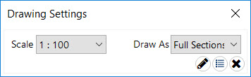
The Drawing Settings dialog opens.
Draw Section @X = location
or
Draw Section @Z = location
-
Select the
Scale for your drawing from the drop-down
list.
The Scale of drawing can be set as 1:25, 1:50, 1:80, or 1:100.
-
Select an option from the
Draw As drop-down list.
This will control the extents of how members are drawn.
- Either:

Tip: Alternatively, you can use the options in the Drawing
List tab to select Section @X or Section @Z from the
Type drop-down list to create a plan drawing at a
selected Location.
If you selected to add this drawing to the
drawing list, then click the
 Draw tool below the list on the
Drawing List tab to generate all of your
drawings.
Draw tool below the list on the
Drawing List tab to generate all of your
drawings.