D9.C.4 Built-in Japanese Steel Section Library
The following information is provided for use when the built-in steel tables are to be referenced for member property specification. These properties are stored in a database file. If called for, these properties are also used for member design. Since the shear areas are built into these tables, shear deformation is always considered for these members during the analysis. An example of member property specification in an input file is provided at the end of this section.
A complete listing of the sections available in the built-in steel section library may be obtained using the tools of the graphical user interface.
Following are the descriptions of different types of sections.
D9.C.4.1 I shapes
I shapes are specified in the following way:

1 TO 9 TA ST I300X150X11
12 TO 15 TA ST I350X150X9
D9.C.4.2 H shapes
H shapes are specified as follows:
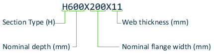
1 TO 8 TA ST H200X100X4
13 TO 17 TA ST H350X350X12

D9.C.4.4 Channels
Channel sections are specified as follows.

25 TO 34 TA ST C125X65X6
46 TO 49 TA ST C200X90X8
D9.C.4.5 Double Channels
Back to back double channels, with or without a spacing in between them, are available. The letter D in front of the section name is used to specify a double channel. Front-to-front double channels are similarly added by adding FR in front of the section name.
17 TO 27 TA D C300X90X10
45 TO 76 TA D C250X90X11 SP 2.0
28 TO 30 TA FR C200X90X8 SP 2.5
In the above commands, members 17 to 27 are a back-to-back double channels C300X90X10 with no spacing in between. Members 45 to 76 are a double channels C250X90X11 with a spacing of 2 length units. Members 28 to 30 are front-to-front double channels C200X90X8 with a spacing of 2.5 length units.
D9.C.4.6 Angles
Two types of specification may be used to describe an angle. The standard angle specification is as follows.
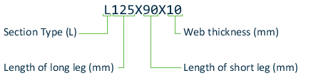
The letter L (signifying that the section is an angle) is followed by the length of the legs and then the thickness of the leg, all in millimeters. The word ST signifies that the section is a standard angle meaning that the major principal axis coincides with the local YY axis specified in G.4.2 Local Coordinate System .
1 4 TA ST L150X90X9
If the minor principal axis coincides with the local YY axis specified in Chapter 2 of the User's Manual, the word RA (Reverse Angle) should be used instead of ST as shown below.
7 TO 23 TA RA L90X75X9
D9.C.4.7 Double angles
Short leg back-to-back and long leg back-to-back double angles may be specified by using the words SD or LD in front of the angle size. In the case of an equal angle, either SD or LD will serve the purpose. The spacing between the angles may be specified by using the word SP after the angle size followed by the value of the spacing.
8 TO 25 TA SD L100X65X7 SP 2.0
36 TO 45 TA LD L300X90X11 SP 3.0
The first example indicates a short legs back-to-back double angle comprised of 100X65X7 angles separated by 2 length units. The latter is a long legs back-to-back double angle comprised of 300X90X11 angles separated by 3 length units.
D9.C.4.8 Tubes
Tube names are input by their dimensions. For example,
6 TA ST TUBE DT 8.0 WT 6.0 TH 0.5
is a tube that has a height of 8 length units, width of 6 length units and a wall thickness of 0.5 length units. Only code checking, no member selection can be performed on TUBE sections.
D9.C.4.10 Pipes (General Pipe sections)
Circular hollow sections defined by JIS G3444:2005 Design Standard for Steel Structures - Based on Allowable Stress Concept as general pipe sections are specified as shown in the following example.
1 TO 9 TA ST PIPE PIP267.4x7.0
specifies a pipe with outside diameter of 267.0 mm and a thickness of 7.0 mm. Only code checking, no member selection, can be performed on PIPE sections.
D9.C.4.11 Circular Hollow sections
Circular hollow sections defined by JIS G3475:2005 Design Standard for Steel Structures - Based on Allowable Stress Concept as Architectural pipe sections are specified as shown in the following example.
1 TO 9 TA ST PIPE CHS660.4x16
specifies a pipe with outside diameter of 660.4 mm and a thickness of 16.0 mm. Only code checking, no member selection, can be performed on CHS sections.
D9.C.4.12 Rectangular Hollow sections
Rectangular hollow sections defined by JIS G3466:2005 Design Standard for Steel Structures - Based on Allowable Stress Concept are specified as shown in the following example.
1 TO 9 TA ST PIPE RHS200x100x12
specifies a tube with a depth of 200 mm, a width of 100 mm, and a thickness of 12 mm. Only code checking, no member selection, can be performed on RHS sections.
D9.C.4.13 Square Hollow sections
Square hollow sections defined by JIS G3466:2005 Design Standard for Steel Structures - Based on Allowable Stress Concept are specified as shown in the following example.
1 TO 9 TA ST PIPE SHS200xs00x12
specifies a square tube with a width of 200 mm and a thickness of 12 mm. Only code checking, no member selection, can be performed on SHS sections.
D9.C.4.14 Example
The following is a sample input file containing Japanese shapes.
STAAD  SPACE
UNIT  KIP FEET
JOINT  COORD
1  0 0 0 12 11 0 0
MEMB  INCIDENCE
1  1 2 11
UNIT  INCH
MEMBER  PROPERTY JAPANESE
*  H-SHAPE
1  TA ST H200X100X4
*  I SHAPE
2  TA ST I250X125X10
*  T SHAPE
3  TA ST T200X19
*  CHANNEL
4  TA ST C125X65X6
*  DOUBLE CHANNEL
5  TA D C200X90X8
*  REGULAR ANGLE
6  TA ST L100X75X7
*  REVERSE ANGLE
7  TA RA L90X75X9
*  DOUBLE ANGLE - LONG LEG BACK TO BACK
8  TA LD L125X75X7 SP 2.0
*  DOUBLE ANGLE - SHORT LEG BACK TO BACK
9  TA SD L300X90X11 SP 1.5
*  TUBE
10  TA ST TUBE DT 3.0 WT 2.5 TH 0.25
*  PIPE
11  TA ST PIPE OD 3.0 ID 2.5
PRINT  MEMBER PROPERTIES
FINISH