V. AISC N690 1994 Angle
Verify the allowable stress and critical ratio of the brace members in a frame using the AISC N690 1994 code.
Details
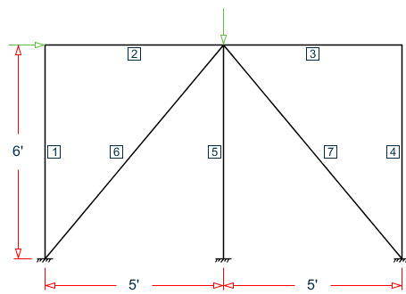
Space frame subjected to static loads
The horizontal load is 7.5 kips and the vertical load is 10 kips.The forces due to loading in member 6 is 2.861 kips (tension) and in member 7 is 7.328 kips (compression). Members 6 and 7 are "truss" members (axial-only).
Both member 6 and 7 are L 80x60x10, austenitic stainless steel (Fy = 36 ksi, Fu = 58 ksi).
Assume a net section factor of 0.9 and an effective length factor of 0.85.
Validation
Slenderness ratio (same for both members) using the minimum value of r: kL/rz = 0.85(93.726)/1.29 = 61.76
For member 6, kL/rz = 61.76 < 300
For member 7, kL/rz = 61.76 < 200
For members in compression (member 7), the equivalent slenderness ratio per Eqn. 4-4 of AISC ASD p5-311 must also be determined:
| (KL/r)equiv = π×√(E/Fe) |
| = |
Thus, (KL/r)equiv = π×√(29,000/60.348) = 68.86
Axial Tension: Member 6
Actual tensile stress (gross) = P/A = 2.862 / 8.41 = 0.340 ksi
Allowable tensile stress (Tension capacity) = 0.6×Fy = 0.6×36 = 21.6 ksi
Critical ratio = 0.340/21.6 = 0.016
Axial Compression: Member 7
Actual compressive stress = P/A = 7.328 / 8.41 = 0.871 ksi
As this member is made from austenitic stainless steel the allowable compression stress should be determined according to clause Q.1.5.9. As KL/r < 120, then the value of allowable axial stress, Fa, is determined from Eqn. Q1.5-11:
Check cross-section meets requirements of Q1.9, which sets a limit for any unstiffened element clause Q1.9.1.2 of 75/√(Fy) = 12.67
- Short leg = B/t = 6/0.625 = 9.5 < 12.67, OK
- Long leg = D/t = 8/0.625 = 12.8 > 12.67, leg is slender
Since 75/√(Fy) = 12.67 < D/t = 12.8 < 155/√(Fy) = 25.83, Qs is determined by Eqn. QC2-1:
Qs = 1.340 - 0.00447×(b/t)×√(Fy) = 0.9967
Allowable compressive stress, Fa = 0.9967 × 10.57 = 10.54 ksi
Critical ratio = 0.871 / 10.54 = 0.083
Results
| Parameter | Hand Calculation | STAAD.Pro | Difference | Comments | |
|---|---|---|---|---|---|
| Member 6 (tension) | Slenderness ratio | 61.76 | 61.76 | negligible | |
| Actual tensile stress (ksi) | 340 | 340 | none | ||
| Allowable tensile stress (ksi) | 21.6 | 21.6 | none | ||
| Critical ratio | 0.016 | 0.016 | none | ||
| Member 7 (compression) | Critical slenderness ratio | 68.86 | 68.87 | negligible | |
| Actual tensile stress (ksi) | 0.871 | 0.87 | negligible | ||
| Allowable compressive stress (ksi) | 10.54 | 10.55 | negligible | ||
| Critical ratio | 0.083 | 0.083 | none | ||
STAAD Input
The file C:\Users\Public\Public Documents\STAAD.Pro 2023\Samples \Verification Models\09 Steel Design\US\AISC\AISC N690 1994 Angle.STD is typically installed with the program.
STAAD SPACE
START JOB INFORMATION
ENGINEER DATE 26-Aug-18
END JOB INFORMATION
INPUT WIDTH 79
**************************************************************
UNIT INCHES POUND
JOINT COORDINATES
1 0 0 0; 2 60 0 0; 3 120 0 0; 4 0 72 0; 5 120 72 0; 6 60 72 0;
MEMBER INCIDENCES
1 1 4; 2 4 6; 3 6 5; 4 5 3; 5 6 2; 6 1 6; 7 6 3;
DEFINE MATERIAL START
ISOTROPIC STEEL
E 2.9e+07
POISSON 0.3
DENSITY 0.283
ALPHA 1.2e-05
DAMP 0.03
TYPE STEEL
STRENGTH FY 36000 FU 58000 RY 1.5 RT 1.2
END DEFINE MATERIAL
MEMBER PROPERTY AMERICAN
1 TO 5 TABLE ST W8X48
6 7 TABLE ST L806010
CONSTANTS
MATERIAL STEEL ALL
SUPPORTS
1 TO 3 FIXED
MEMBER TRUSS
6 7
PRINT MEMBER PROPERTIES all
LOAD 1 LOADTYPE None  TITLE LOAD CASE 1
JOINT LOAD
4 FX 7500
6 FY -10000
PERFORM ANALYSIS
************************************************************
PARAMETER 1
CODE AISC N690 1994
* Material strength
FU 58000  MEMB 6 7
FYLD 36000  MEMB 6 7
* Net area reduced by 10%
NSF 0.9 MEMB 6 7
* Austenitic stainless steel
STYPE 1  MEMB 6 7
* Effective length factors 0.85 in both axes
LX 1 MEMB 6 7
KY 0.85  MEMB 6 7
KZ 0.85  MEMB 6 7
*
TRACK 2 ALL
CHECK CODE MEMB 6 7
FINISH
STAAD Output
                       STAAD.PRO CODE CHECKING - (  ANSI N690-1994)   v1.0
                       ********************************************
  |--------------------------------------------------------------------------|
  |                                                    Y        PROPERTIES   |
  |*************                                       |        IN INCH UNIT |
  |            *  |=============================|   ==| |==     ------------ |
  |MEMBER   6  *  |  AISC SECTIONS              |     | |       AX =   8.41  |
  |            *  | ST  L806010                 |     | |  --Z  AY =   3.33  |
  |DESIGN CODE *  |                             |     | |       AZ =   2.50  |
  |ANSI N690-94*  ===============================   ==| |==     SY =  11.99  |
  |            *                                                SZ =   5.16  |
  |            *  |<---LENGTH (FT)=    7.81 --->|               RY =   2.81  |
  |*************                                                RZ =   1.29  |
  |                                                                          |
  |                  0.0 (KIP-FEET)                                          |
  |PARAMETER        |L0                                     L0  STRESSES     |
  |IN KIP  INCH     |L0                                     L0  IN KIP  INCH |
  |---------------  +L0                                     L0  -------------|
  | KL/R-Y=  28.34  |L0                                     L0  FA  =  21.60 |
  | KL/R-Z=  61.76  +L0                                     L0  fa  =   0.34 |
  | UNL   =  93.72  |L0                                     L0  FCZ =   0.00 |
  | CB    =   0.00  +L0                                     L0  FTZ =   0.00 |
  | CMY   =   0.00  |L0                                     L0  FCY =   0.00 |
  | CMZ   =   0.00  +L0                                     L0  FTY =   0.00 |
  | FYLD  =  36.00  |L0                                     L0  fbz =   0.00 |
  | NSF   =   0.90  +---+---+---+---+---+---+---+---+---+---|   fby =   0.00 |
  | DFF   =   0.00   0.0                                        Fey = 165.72 |
  | dff=      0.00               ABSOLUTE MZ ENVELOPE           Fez =  34.91 |
  | (KL/R)max =  68.87              (WITH LOAD NO.)             FV  =   0.00 |
  |                                                             fv  =   0.00 |
  |                                                                          |
  |                      MAX FORCE/ MOMENT SUMMARY  (KIP-FEET)               |
  |                      -------------------------                           |
  |                                                                          |
  |                AXIAL      SHEAR-Y    SHEAR-Z    MOMENT-Y    MOMENT-Z     |
  |                                                                          |
  |      VALUE      -2.9         0.0        0.0         0.0         0.0      |
  |   LOCATION       0.0         0.0        0.0         0.0         0.0      |
  |    LOADING         1           0          0           0           0      |
  |                                                                          |
  |**************************************************************************|
  |*                                                                        *|
  |*                         DESIGN SUMMARY  (KIP-FEET)                     *|
  |*                         --------------                                 *|
  |*                                                                        *|
  |*       RESULT/     CRITICAL COND/     RATIO/         LOADING/           *|
  |         FX              MY             MZ           LOCATION             |
  |        ======================================================            |
  |          PASS        ANSI Q1.6-2      0.016              1               |
  |          2.86 T          0.00         0.00             0.00              |
  |*                                                                        *|
  |                                                                          |
  |--------------------------------------------------------------------------|
      STAAD SPACE                                              -- PAGE NO.    5
                       STAAD.PRO CODE CHECKING - (  ANSI N690-1994)   v1.0
                       ********************************************
  |--------------------------------------------------------------------------|
  |                                                    Y        PROPERTIES   |
  |*************                                       |        IN INCH UNIT |
  |            *  |=============================|   ==| |==     ------------ |
  |MEMBER   7  *  |  AISC SECTIONS              |     | |       AX =   8.41  |
  |            *  | ST  L806010                 |     | |  --Z  AY =   3.33  |
  |DESIGN CODE *  |                             |     | |       AZ =   2.50  |
  |ANSI N690-94*  ===============================   ==| |==     SY =  11.99  |
  |            *                                                SZ =   5.16  |
  |            *  |<---LENGTH (FT)=    7.81 --->|               RY =   2.81  |
  |*************                                                RZ =   1.29  |
  |                                                                          |
  |                  0.0 (KIP-FEET)                                          |
  |PARAMETER        |L0                                     L0  STRESSES     |
  |IN KIP  INCH     |L0                                     L0  IN KIP  INCH |
  |---------------  +L0                                     L0  -------------|
  | KL/R-Y=  28.34  |L0                                     L0  FA  =  10.55 |
  | KL/R-Z=  61.76  +L0                                     L0  fa  =   0.87 |
  | UNL   =  93.72  |L0                                     L0  FCZ =   0.00 |
  | CB    =   0.00  +L0                                     L0  FTZ =   0.00 |
  | CMY   =   0.00  |L0                                     L0  FCY =   0.00 |
  | CMZ   =   0.00  +L0                                     L0  FTY =   0.00 |
  | FYLD  =  36.00  |L0                                     L0  fbz =   0.00 |
  | NSF   =   0.90  +---+---+---+---+---+---+---+---+---+---|   fby =   0.00 |
  | DFF   =   0.00   0.0                                        Fey = 165.72 |
  | dff=      0.00               ABSOLUTE MZ ENVELOPE           Fez =  34.91 |
  | (KL/R)max =  68.87              (WITH LOAD NO.)             FV  =   0.00 |
  |                                                             fv  =   0.00 |
  |                                                                          |
  |                      MAX FORCE/ MOMENT SUMMARY  (KIP-FEET)               |
  |                      -------------------------                           |
  |                                                                          |
  |                AXIAL      SHEAR-Y    SHEAR-Z    MOMENT-Y    MOMENT-Z     |
  |                                                                          |
  |      VALUE       7.3         0.0        0.0         0.0         0.0      |
  |   LOCATION       0.0         0.0        0.0         0.0         0.0      |
  |    LOADING         1           0          0           0           0      |
  |                                                                          |
  |**************************************************************************|
  |*                                                                        *|
  |*                         DESIGN SUMMARY  (KIP-FEET)                     *|
  |*                         --------------                                 *|
  |*                                                                        *|
  |*       RESULT/     CRITICAL COND/     RATIO/         LOADING/           *|
  |         FX              MY             MZ           LOCATION             |
  |        ======================================================            |
  |          PASS        ANSI Q1.6-2      0.083              1               |
  |          7.33 C          0.00         0.00             0.00              |
  |*                                                                        *|
  |                                                                          |
  |--------------------------------------------------------------------------|