D5.A.5.4.1 Basic stress check
This method is used when the TORSION parameter is specified as one (1).
This method is intended to be a simplified stress check for torsional effects per Cl. 6.2.7(5). Any warping stresses that may develop due to the end conditions will be ignored for this option. The program will consider the forces (including torsion) at various sections along the length of the member and for each section, will calculate the resultant stress (Von Mises) at various points on the cross section. The location and number of points checked for a cross section will depend on the cross section type and will be as described below.
The stress check will be performed using equation 6.1 of EN 1993-1-1:2005 as given below:
where| = | ||
| = | ||
| = |
σx,Ed = σx + σbz + σby = Fx/Ax + Mz/Zz + My/Zy
τEd = T/J · t + Vy·Q/(Iz·t) + Vz·Q/(Iy*t)
where| = | ||
| = | ||
| = | ||
| = | ||
| = | ||
| = |
The stress check as per equation 6.1 is performed at various stress points of a cross section as shown in figures below:
| Shape | Section Sketch |
|---|---|
| Doubly symmetric wide flange profile |
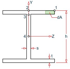
|
|
Pipe profiles α = tan-1(Mz/My) |
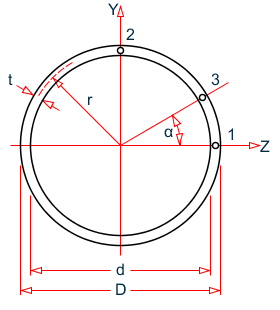
|
| Tube profiles |
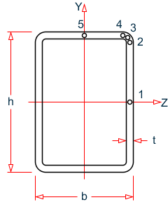
|
| Channel profiles |
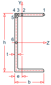
|
The resultant ratio will be reported under Cl. 6.2.7(5) in the detailed design output.