M.To create a tee user table section
To create a user-provided table section with a tee profile, use the following procedure.
You may want to change the input dimensions prior to creating user provided table sections. Select to do so.
-
On the
Specification ribbon tab, select the
tool in the
Beam Profiles group.

If no User Defined Table exists, you will be prompted to create one.
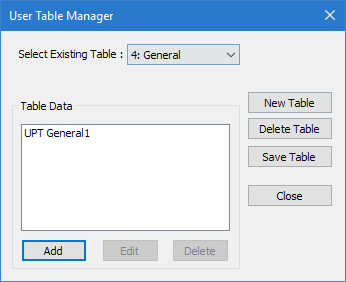
The User Table Manager dialog opens. - Click New Table. The New User Table dialog opens.
- In the Select Section Type list, select TEE and then click OK. The dialog closes and the Table Data list in the User Table Manager dialog now has at least one entry.
-
Click Add.
The Tee dialog opens.
- Type a Section Name.
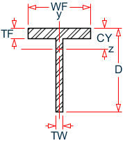
- Required: Enter the following angle section parameters:
-
Specify the section properties by typing the following values:
- Cross Section Area (Ax)
- Cross section area.
- Inertia about local z (Iz)
- Moment of inertia about local z-axis (usually strong axis)
- Inertia about local y (Iy)
- Moment of inertia about local y-axis
- IX
- Torsional constant
- C.G. along local Y (Cy)
- Distance from back of web to center of gravity (C.G.) of the shape along the local y-axis.
- Shear Area in Y (Ay)
- Shear area in local y-axis. If zero, shear deformation is ignored in the analysis.
- Shear Area in Z (Az)
- Shear area in local z-axis. If zero, shear deformation is ignored in the analysis.
- Click OK.
- (Optional) Repeat steps 4 through 8 to add more tee sections.
- Click Close.
The section can now be added for use in the Properties - Whole Structure dialog by selecting it in the User Property Table dialog.
Refer to
EX. US-17 User-Provided Tables
and
EX. UK-17 User-Provided Tables
for examples of angle user-provided tables.