V. ACI 318-14 Rectangular Beam without Torsion
Design of a doubly reinforced rectangular beam.
Details
Determine the required area of tension and compression reinforcement.
The beam cross-section is limited to size 14in X 23 in. The factored moment Mu= 516 ft-kips.
f'c= 4000psi, fy=60,000 psi.
Validation
dcover = 2.5 in
Check if Compression Reinforcement is Required
Use Ζ = 0.9.
Refer to table 6-1 of PCA Notes (ref. 2).
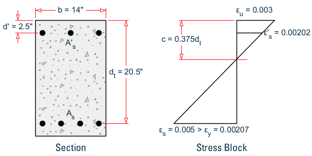
b = 14 in
d = 20.5 in
Mn = Mu/Ζ = 573.33 ft-kip
Rn = Mn / (b*d2) = 1.169(10)3 psi
Rnt = 911 psi
Rn > Rnt
Hence, both compression and tension reinforcement is required.
Max. Moment with Compression Reinforcement
Mnt
This condition corresponds to tension controlled limit (Ζ = 0.9).
Depth of neutral axis, c = 0.375dt = 0.375d = 7.687 in
β1 = 0.85 (from table 6.1 (ref. 2)
a = β1*c = 6.534 in
Compressive force, C = 0.85·fc·a·b = 311.036 kips
Tension force, T = C = 311.036 kips
Nominal moment strength resisted by the concrete section, without compression reinforcement, Mnt = T(d - a/2) = 446.669 ft-kips
Nominal moment strength resisted by the concrete section, with compression reinforcement, Mnc = Mn - Mnt = 126.664 ft-kips
Area of Tension Steel
Area of tension steel required, As,nt , to develop Mnt
As,nt = T / fy = 5.184 in2
Additional Area of Tension Steel
Area of tension steel required, As,additional , required to counteract additional moment due to T-C couple.
As,additional = (Mn - Mnt) / [ fy· (d - dcover)] = 1.407 in2
Total tension steel required:
As = As + As,nt = 6.591 in2
Comparison
| Parameter | Reference | STAAD.Pro | Difference | Comments |
|---|---|---|---|---|
| Area Required (compression) (in2) | 1.441 | 1.61 | 11.0 | The required steel calculation assumes a single layer of bottom bars and the effective depth = 0.375×dt based on the single bar layer. The reference (ref. 2) calculations only considers a strength design and does not check for the minimum spacing requirements. STAAD.Pro however considers two layers of bars in the design to account for the minimum criteria and hence uses a neutral axis position based on the two bar layers. Thus the minor difference in the steel areas calculated. |
| Area Required (tension) (in2) | 6.591 | 6.355 | 3.6% |
STAAD Input
The file C:\Users\Public\Public Documents\STAAD.Pro 2023\Samples \Verification Models\10 Concrete Design\US\ACI 318-14 Rectangular Beam Without Torsion.std is typically installed with the program.
STAAD SPACE
START JOB INFORMATION
***********************************************************************
* This example is a replica of example no 6.2 of PCA Notes 318-11.

***********************************************************************
ENGINEER DATE 29-Aug-18
JOB NAME PCA Example 6.2
JOB CLIENT Bentley Systems Inc.
ENGINEER NAME TK
END JOB INFORMATION
INPUT WIDTH 79
UNIT FEET KIP
JOINT COORDINATES
1 0 0 0; 2 8 0 0;
MEMBER INCIDENCES
1 1 2;
DEFINE MATERIAL START
ISOTROPIC CONCRETE
E 453600
POISSON 0.17
DENSITY 0.14999
ALPHA 5.5e-06
DAMP 0.05
TYPE CONCRETE
STRENGTH FCU 576
END DEFINE MATERIAL
MEMBER PROPERTY AMERICAN
1 PRIS YD 1.91667 ZD 1.16667
CONSTANTS
MATERIAL CONCRETE ALL
SUPPORTS
1 FIXED
LOAD 1 LOADTYPE Dead  TITLE LOAD CASE 1
JOINT LOAD
2 MZ 464.417
PERFORM ANALYSIS
PRINT SUPPORT REACTION ALL
START CONCRETE DESIGN
CODE ACI
UNIT INCHES KIP
MAXMAIN 8 ALL
MINMAIN 8 ALL
*MIMB 6 ALL
*MXMB 6 ALL
CLT 2 ALL
CLB 2 ALL
TRACK 2 ALL
DESIGN BEAM ALL
END CONCRETE DESIGN
FINISH
STAAD Output
                       STAAD.PRO CONCRETE DESIGN - (ACI-318-14)   v2.0
                       ***********************************************
Units: KIP   , INCHES (Unless Noted Otherwise)
 Member :      1
DESIGN SUMMARY
-----------------------------------------------------------------------------
| Status         :   Pass         Type    : Beam            Length:   96.000 |
| Critical Ratio :   0.910        Criteria: Flexure                          |
| Critical Clause:   9.5.2                                                   |
-----------------------------------------------------------------------------
CROSS SECTION
-------------------------------------------------------
| Shape: Rectangular | Width:   14.00 | Depth:   23.00 |
-------------------------------------------------------
DESIGN INPUTS
-------------------------------------------------------------------------
| Concrete | Fc           4.000 |                     | Ec     0.360E+04 |
| Steel    | Fy(main)    60.000 | Fy(trans)    60.000 | Es     0.290E+05 |
| Cover    | Top          2.000 | Bottom        2.000 | Sides      1.500 |
-------------------------------------------------------------------------
CRITICAL STRENGTH RESULTS
-----------------------------------------------------------------------
| Category |    Demand     |  Min Capacity  |  Max Capacity  |  Ratio  |
-----------------------------------------------------------------------
| Axial    |          0.000|       -871.565 |        554.580 |   0.000 |
| Flexure  |       5573.004|      -2586.136 |       6122.188 |   0.910 |
| Shear Y  |          0.000|        -24.729 |         24.729 |   0.000 |
| Shear Z  |          0.000|        -26.729 |         26.729 |   0.000 |
| Torsion  |          0.000|          0.000 |          0.000 |   0.000 |
-----------------------------------------------------------------------
LONGITUDINAL BAR DETAILS AT CROSS SECTIONS
---------------------------------------------------------------------------------
| Distance | Position |  Ast-reqd  |  Ast-prov  | No(s)bars| Size | No of Layers |
---------------------------------------------------------------------------------
|    0.000 |     Top  |      1.610 |      2.370 |     3    |  # 8 |       1      |
|          |  Bottom  |      6.355 |      7.900 |    10    |  # 8 |       2      |
|   24.000 |     Top  |      1.610 |      2.370 |     3    |  # 8 |       1      |
|          |  Bottom  |      6.355 |      7.900 |    10    |  # 8 |       2      |
|   48.000 |     Top  |      1.610 |      2.370 |     3    |  # 8 |       1      |
|          |  Bottom  |      6.355 |      7.900 |    10    |  # 8 |       2      |
|   72.000 |     Top  |      1.610 |      2.370 |     3    |  # 8 |       1      |
|          |  Bottom  |      6.355 |      7.900 |    10    |  # 8 |       2      |
|   96.000 |     Top  |      1.610 |      2.370 |     3    |  # 8 |       1      |
|          |  Bottom  |      6.355 |      7.900 |    10    |  # 8 |       2      |
---------------------------------------------------------------------------------
      STAAD SPACE                                              -- PAGE NO.    6
LONGITUDINAL BAR LAYOUT
---------------------------------------------------------------------------
|                |    Bars     |      Location     | Distance  |   Anchor  |
|       Position | Nums | Size | Start  |   End    | From Face | Start End |
---------------------------------------------------------------------------
|            Top |    3 | # 8  |    0.00|    96.00 |     2.50  |  Yes  Yes |
|         Bottom |    5 | # 8  |    0.00|    96.00 |     2.50  |  Yes  Yes |
|         Bottom |    5 | # 8  |    0.00|    96.00 |     4.50  |  Yes  Yes |
---------------------------------------------------------------------------
TRANSVERSE BAR LAYOUT
------------------------------------------------------------------------------------
|                                |        Asv        |     Rebar Specification      |
| Zone | Dir.|  From   |    To   |  Reqd.  |  Prov.  | Nums | Size | Spacing | Legs |
------------------------------------------------------------------------------------
|    1 |  Y  |    0.00 |   96.00 |  0.0286 |  0.0292 |    8 |  # 4 |  13.71  |   2  |
|    1 |  Z  |    0.00 |   96.00 |  0.0286 |  0.0292 |    8 |  # 4 |  13.71  |   2  |
------------------------------------------------------------------------------------
------------------------ Member:     1 Design Ends ------------------------