The cross section capacity of a member subject to bending is checked as per Cl .6.2.5 of the code. The condition to be satisfied is:
where
| Mc,Rd | = | the is the design resistance given by:
-
for class 1 and 2 cross-sections
-
for class 3 cross-sections
-
for class 4 cross-sections
|
Cross sectional bending capacity checks will be done for both major and minor
axis bending moments.
Members subject to major axis bending will also be checked for
lateral-torsional buckling resistance as per Section 6.3.2 of the code. The design buckling
resistance moment Mb,Rd will be calculated as:
where
| χLT | = | the reduction factor for lateral-torsional buckling. This
reduction factor is evaluated per Cl. 6.3.2.2 or Cl 6.3.2.3 of the EN 1993 code
depending on the section type. For I sections, the program will by default use Cl.
6.3.2.3 to evaluate χLT and for all other sections the program will
resort to Cl 6.3.2.2. However, if a particular National Annex has been specified,
the program will check if the National Annex expands on Cl.6.3.2.3 (Table 6.5) to
include sections other than I sections. If so, the program will use Cl. 6.3.2.3
for the cross-section(s) included in Cl. 6.2.2.3 (or Table 6.5). For all other
cases the program will use Cl. 6.3.2.2. |
Note: You have the option to choose the clause
to be used to calculate χ
LT through the
MTH design parameter.
Setting
MTH to
0 (default value) will cause the
program to choose Cl.6.3.2.3 for I Sections and Cl 6.2.3.2 for all other section types. As
mentioned above, if the National Annex expands on Cl. 6.3.2.3 to include sections other
than I Sections, the program will use Cl. 6.3.2.3 by default.
When using Cl. 6.3.2.3 to calculate χLT, the program will consider
the correction factor kc (Table 6.6 of EN 1993-1-1:2006) based on the value of the
KC parameter in the design input. By default the value of
KC will be taken as 1.0. If you want the program to calculate kc, you must
explicitly set the value of the KC parameter to zero.
Note: If the National Annex specifies a
different method to calculate
kc (e.g. the British, Singapore & Polish NAs), the program
will use that method by default even if the KC parameter has not been explicitly set to
zero. If the NA method does not deal with a specific condition while working out kc, the
program will then fall back to table 6.6 of the code, thus ensuring that kc is considered
for the particular NA.
The non-dimensional slenderness λ
LT (used to evaluate χLT) for both the above cases is evaluated
as:
where
| Mcr | = | the elastic critical moment for lateral-torsional buckling. EN
1993-1-1 does not however specify a method to evaluate Mcr. Hence, the
program will make use of the method specified in Annex F of DD ENV 1993-1-1 to
evaluate Mcr by default. |
Note: The method specified in Annex F will be
used only when the raw EN 1993-1-1:2005 code is used without any National Annex. If a
National Annex has been specified, the calculation of
Mcr (and
) will be done based on the specific National Annex. (Refer to
D5.B. European Codes - National Annexes to Eurocode 3 [EN
1993-1-1:2005]
for specific details). If the National Annex does not specify a particular method or
specify a reference document, the program will use the NCCI document SN-003a-EN-EU for
doubly symmetric sections and SN030a-EN-EU for mono-symmetric sections that are symmetric
about their weak axis. For all other sections types the program will use Annex F of DD ENV
1993-1-1 to calculate
Mcr. In cases where Annex F does not provide an adequate method
to evaluate
Mcr, such as for Channel sections, the program will resort to
the method as per Cl.4.3.6 of BS 5950-1:2000 to calculate the lateral-torsional buckling
resistance moment (
Mb,Rd) for the member.
D5.A.5.2.1 Tapered Members
EN 1993-1-1 provides multiple methods for checking against
lateral-torsional buckling in members with tapered I-shaped sections. The method given
in Annex BB 3.2 of EN 1993-1-1 is used by STAAD.Pro. This
method checks the unbraced length between lateral and torsional restraints against a
calculated maximum length to ensure lateral-torsional stability. The tapered member is
sub-divided into thirteen (13) analytical sections and bending design checks, including
these for lateral-torsional buckling, are performed at each sub-section. While this
approach is conservative for elastic analysis, it is necessary for plastic analysis.
The stable length between lateral restraints, Lm,
is calculated as follows. This value must be greater than or equal to the design
parameter LY.
| (Eqn. BB.5) |
where
| rzz | = | the radius of gyration about the major axis ( notation
iz in EN 1993-1-1) |
| NEd | = | design value of compression force in the member |
| A | = | cross-sectional area of the member |
| Wpl,y | = | plastic section modulus of the member |
| IT | = | torsional constant |
| fy | = | yield strength |
| C1 | = | a factor depending on loading and end conditions; taken
, where kc is taken from the KC
parameter. |
The stable length between torsional restraints, Ls,
is calculated as follows. This value must be greater than or equal to the design
parameter EFT.
| (Eqn. BB.12) |
where
| Cn | = | modification factor for non-linear moment gradient
| (Eqn. BB.14) |
|
| R | = | moment ratio calculated at ends, quarter points, and
mid-point of member segment between torsional restraints, calculated as:
| (Eqn. BB.15) |
and R1 is taken from the largest web
depth.
|
| My,Ed | = | design bending moment about the Y axis |
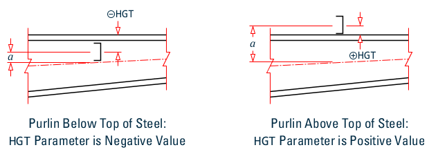
| a | = | the distanced between the centroid of the member and the
centroid of the restraining members (e.g., purlins). Note: This value is controlled in
STAAD.Pro using the HGT
parameter. To simplify the user input, the HGT parameter is
specified in relation to the top of the member.
|
| Lk | = | stable length between adjacent torsional restraints
| (Eqn. BB6) |
and is taken from the shallowest web depth.
|
| E | = | modulus of elasticity |
| c | = | taper factor:
| (Eqn. BB.16) |
|
| h | = | depth of segment |
| tf | = | thickness of the flange |
|
hmax, hmin | = | the maximum and minimum depth of the cross-section within
the length, Ly (LY), respectively. |
Note: There are no provisions for
lateral-torsional buckling in tapered hollow sections (i.e., tapered square or circular
sections). As this is typically not a governing limit state,
STAAD.Pro does not perform any such check.