T.1 Creating Load Cases 1 and 2
Load cases 1 and 2 are primary load cases. These load cases are used during analysis of the structure.
- Change the length units to Feet by selecting the length unit in the application window status bar. See T.1 Changing the input units of length.
-
On the
Loading ribbon tab, select the
Primary Load Case in the
Loading Specifications group.

-
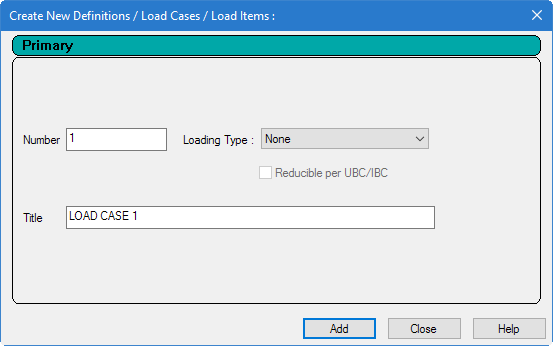
Enter the properties for the first load case:
-
Type
DEAD + LIVE in the
Title field.
Leave the Number as the default value of 1.
Note: The Loading Type list is used to associate the load case we are creating with any of the ACI, AISC, IBC, or other code-prescribed definitions of Dead, Live, Ice, etc. This type of association needs to be done if you intend to use the program's automatically generating load combinations in accordance with those codes. Note that there is a check box labeled Reducible per UBC/IBC. This feature is active only when the load case is assigned a Loading Type called Live when you create that load case.Since this tutorial does not use the automatic load combination generation feature, leave the Loading Type as None.
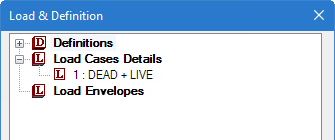
- Click Add. The load case appears under the Load Cases Details option in the Load & Definition dialog.
- Click Close.
-
Type
DEAD + LIVE in the
Title field.
-
On the
Loading ribbon tab, select the
Load Items tool in the
Loading Specifications group.

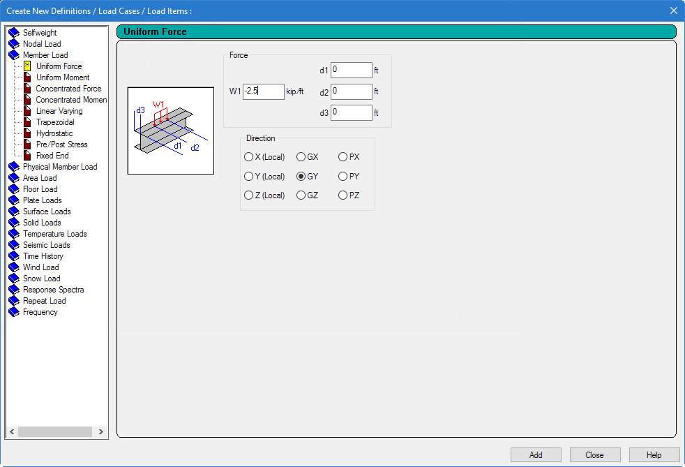
The Create New Load Items dialog opens with entries for adding load items to the current load case. - Define the uniform load for this load case:
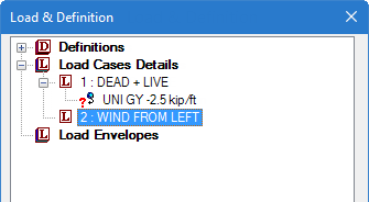
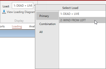
- Repeat steps 2 and 3 to create the second load case, except title the load case as WIND FROM LEFT.
- Set the wind load case as the current load case: Load items created using the ribbon tab tools are added to the current load case.
-
On the
Loading ribbon tab, select the
Load Items in the
Loading Specifications group.
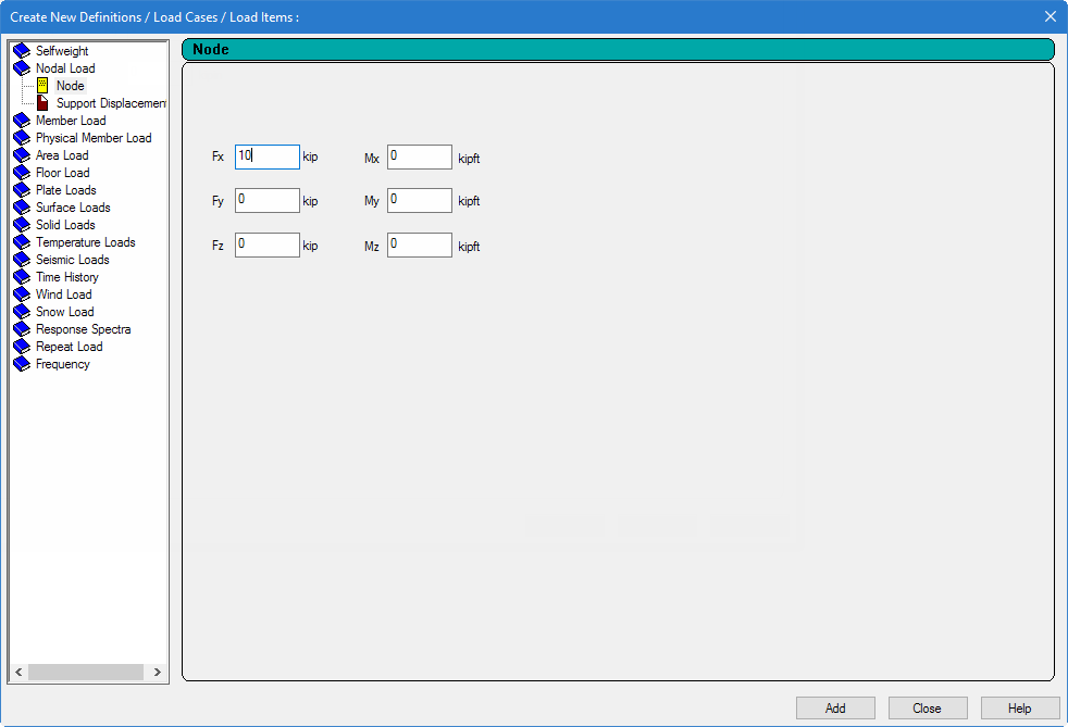
The Create New Load Items dialog opens with entries for adding load items to the selected load case. - Define the wind load at the joint: