V. AISC LRFD - Select Wide Flange 2
To find the optimum W shape with a flexural design strength of 150 ft·kips. Beam is braced at ends and at mid-span point.
Reference
AISC. Load and Resistance Factor Design Specification, 3rd Edition. 1999. Example 5.4, page 5-21.
AISC. Manual of Steel Construction, 3rd Edition. 1999.
Details
The beam should also satisfy a deflection limit of 1.0 inches under service load.
| Fy = 50 ksi |
| Length = 20 ft |
| Lb = 10 ft |
Service load of 2.0 kip/ft. Deflection limit under service load = 1.0 in.
Validation
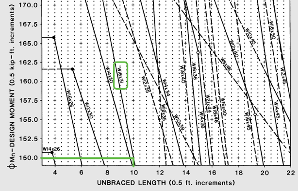
From the chart on p.4-160 of the Manual of Steel Construction, the most efficient wide-flange section to resist 150 kip-ft of moment with an unbraced length of 10 ft is a W16x31. From this same chart, the design bending strength can be taken as 150 kip-ft (the curve crosses at approximately the same point as the demand load).
The deflection limit under service conditions can be met by determining the minimum required moment of inertia needed.
Solving for the minimum I = 248 in4. A W16x31 has an Ix = 375 in4, so it will have less deflection than the limit under service conditions.
Results
| Result Type | Theory | STAAD.Pro | Difference | Comments |
|---|---|---|---|---|
| Optimum Section | W16x31 | W16x31 | none | |
| Design bending strength, ϕbMn (in·kips) | 1,800
(150 ft·kips) |
1,801.66 | negligible | |
| Maximum permissible deflection (in) | 1.0 | 0.6584 | N/A | The STAAD.Pro reported maximum deflection is less than 1.0 in; therefore this section satisfies the requirement. However, this value is not to be directly compared with the limit itself. |
STAAD Input
The file C:\Users\Public\Public Documents\STAAD.Pro 2023\Samples \Verification Models\09 Steel Design\US\AISC\AISC LRFD - Select Wide Flange 2.STD is typically installed with the program.
STAAD SPACE BENDING PER AISC LRFD 3RD ED
START JOB INFORMATION
ENGINEER DATE 23-Sep-18
END JOB INFORMATION
*
*  EXAMPLE 5.4, PAGE 5-21, AISC LRFD 3RD ED.
*  OBJECTIVE : TO FIND THE OPTIMUM W SHAPE WITH A FLEXURAL
*  DESIGN STRENGTH OF 150 KIP-FT.
*
*  ACCORDING TO ABOVE REFERENCE, THE SECTION SHOULD BE W16X31
*
UNIT FEET KIP
JOINT COORDINATES
1 0 0 0; 2 20 0 0;
MEMBER INCIDENCES
1 1 2;
MEMBER PROPERTY AMERICAN
1 TABLE ST W12X26
UNIT INCHES KIP
DEFINE MATERIAL START
ISOTROPIC MATERIAL1
E 29000
POISSON 0.3
END DEFINE MATERIAL
UNIT FEET KIP
CONSTANTS
MATERIAL MATERIAL1 ALL
SUPPORTS
1 PINNED
2 FIXED BUT MZ
LOAD 1
MEMBER LOAD
1 UNI GY -2
LOAD COMBINATION 2
1 1.5
PERFORM ANALYSIS
LOAD LIST 2
UNIT INCHES KIP
PARAMETER 1
CODE LRFD
MAIN 1 ALL
UNT 120 ALL
FYLD 50 ALL
TRACK 1 ALL
SELECT ALL
LOAD LIST ALL
PERFORM ANALYSIS
LOAD LIST 1
SECTION 0.5 ALL
PRINT SECTION DISPL
LOAD LIST 2
CHECK CODE ALL
FINISH
STAAD Output
                       STAAD.Pro MEMBER SELECTION - (LRFD 3RD EDITION)   v1.0
                       **************************
 ALL UNITS ARE - KIP  INCH (UNLESS OTHERWISE Noted)
 MEMBER     TABLE       RESULT/   CRITICAL COND/     RATIO/     LOADING/
                          FX            MY             MZ       LOCATION
 =======================================================================
      1  ST   W16X31                   (AISC SECTIONS)
                           PASS     LRFD-H1-1B-C       0.999         2
                        0.00 C          0.00       -1800.00      120.00
 +---------------------------------------------------------------------+
 | DESIGN STRENGTHS FOR MEMBER     1       UNITS - KIP IN              |
 | PNC=   45.93  PNT=  410.85  MNZ= 1801.66  MNY=  302.71  VN=  118.06 |
 +---------------------------------------------------------------------+
   ************** END OF TABULATED RESULT OF DESIGN **************
    46. LOAD LIST ALL
    47. PERFORM ANALYSIS
    48. LOAD LIST 1
    49. SECTION 0.5 ALL
    50. PRINT SECTION DISPL
  SECTION  DISPL
      BENDING PER AISC LRFD 3RD ED                             -- PAGE NO.    4
     MEMBER SECTION DISPLACEMENTS
     ----------------------------
     UNITS ARE - INCH
     MEMB  LOAD     GLOBAL X,Y,Z DISPL FROM START TO END JOINTS AT 1/12TH PTS
       1     1       0.0000    0.0000    0.0000    0.0000   -0.1731    0.0000
                     0.0000   -0.3331    0.0000    0.0000   -0.4690    0.0000
                     0.0000   -0.5722    0.0000    0.0000   -0.6365    0.0000
                     0.0000   -0.6584    0.0000    0.0000   -0.6365    0.0000
                     0.0000   -0.5722    0.0000    0.0000   -0.4690    0.0000
                     0.0000   -0.3331    0.0000    0.0000   -0.1731    0.0000
                     0.0000    0.0000    0.0000
     MAX LOCAL  DISP =    0.65839   AT     120.00  LOAD    1   L/DISP=    364
         ************ END OF SECT DISPL RESULTS ***********