V. GB500017-2017 H-section with Combined Axial and Bending
Verify the strength, stability, and slenderness of an H section subject to combined axial and bending per GB50017-2017.
Reference
MOHURD. 2017. GB 50017-2017 Standard for design of steel structures . Beijing, China: Ministry of Housing and Urban-Rural Development
Problem
The section is an HN400x408 with a length of 9 m. The structure is a two-story frame. Member #1 assigned with an H-section (HN400x408) is designed per GB 50017-2017. The section has an unbraced length of 4.5 m about the x direction and 9 m about the y direction.
Material Properties
The material is Q235 type steel.
- Design strength in tension, compression, and flexure: fy = 205 MPa
- Design strength in shear: fv = 120 MPa
Section Properties
- Section depth, h = 400 mm
- Section width, b = 408 mm
- Flange thickness, tf = 21 mm
- Web thickness, tw = 21 mm
- Cross-sectional area, A = 25,069 mm2
- Moment of inertia about x, Ix = 708,880,000 mm4
- Moment of inertia about y, Iy = 238,090,000 mm4
- Radius of gyration about x, ix = 168.2 mm
- Radius of gyration about y, iy = 97.5 mm
- Area moment about x, Sx = 3,544,400 mm3
- Area moment about y, Sx = 1,167,100 mm3
Calculations
Slenderness Ratio
The effective length is:
lox = μx×lx = 1.581 × 4,500 mm = 7,115 mm
loy = μy×ly = 1.319 × 9,000 mm = 11,870 mm
The slenderness ratio is:
Ratio for tension slenderness: 42.3 / 150 = 0.28
Ratio for compression slenderness: 121.8 / 150 = 0.81
Steel Grade Correction Factor
The steel type is Q235. According to note 1 in table 3.5.1 of Standard for design of steel structures and table 1 of Standard for design of steel structures. Commentary 2.2, the steel grade correction coefficient is εk = 1.
Overall Stability Coefficient
According to the formula (C.0.1) in Appendix C of Standard for design of steel structures, the overall stability coefficient of the beam determined by the bending around the strong axis is calculated as:
According to the formula (c.0.1-7) in Appendix C of Standard for design of steel structures,
So, for the section in x-x direction, .
Stability Factor for Axial Compression
According to the formula (D.0.5) in Appendix D of Standard for design of steel structures,
For section y-y direction:
Class c, so, the coefficients are α1 = 0.730, α2 = 1.126, and α3 = 0.302.
Since , then the stability factor in y:
For section x-x direction:
Class b, so, the coefficients are α1 = 0.650, α2 = 0.965, and α3 = 0.300.
Since , then the stability factor in x:
Equivalent Moment Factor
The critical buckling load:
For an unbraced frame:
Because there is a reverse bending point, M1 and M2 have different signs:
Section influence coefficient, η = 1.0
Plastic Development Coefficient
According to clause 6.1.2 of Standard for design of steel structures, and the width thickness ratio of cross-section plate is grade S3,
γx = 1.05
γy = 1.20
Check Web Thickness to Height Ratio
Calculated the web height:
h0 = 400 - 21 - 21 = 358 mm
According to table 3.5.1 of Standard for design of steel structures, and the width thickness ratio of cross-section plate is grade S3, so the limit value of height thickness ratio is:
| 40 + 18 × ɑ01.5 |
| = |
| = |
| = |
Therefore, the limit value is: 40 + 18 × 0.0011.5 = 40.00
Ratio:
Check Flange Thickness to Width Ratio
According to table 3.5.1 of Standard for design of steel structures, and the width thickness ratio of cross-section plate is grade S3, so the limit value of width thickness ratio is:
Ratio:Shear Strength
The controlling load condition for shear is combination 10. F : 1.20DL+1.40LL+0.84WL:
Vx = 46.5 kN
Vy = 9.52 kN
Take the neutral axis as the calculation point of shear stress, calculate the area moment:
Sx = 1,960,000 mm3
Sy = 893,700 mm3
According to clause 6.1.3 of Standard for design of steel structures, shear stress
τmax = 6.12 < fv = 120 N/mm2
Therefore, the ratio is:
Check In-plain Stability
The controlling load condition for in-plane stability is combination 14. F : 1.2DL+1.4LL+0.84WF:
Mx = 174.8 kN·m
My = 58.75 kN·m
N = 181.2 kN
According to clause 8.2.5 of Standard for design of steel structures,
| (Cl. 8.2.5) |
Check Out-of-plain Stability
The controlling load condition for in-plane stability is combination 14. F : 1.2DL+1.4LL+0.84WF:
Mx = 174.8 kN·m
My = 58.75 kN·m
N = 181.2 kN
According to clause 8.2.5 of Standard for design of steel structures,
| (Cl. 8.2.5) |
Strength of the Member
The controlling load condition for strength is combination 14. F : 1.2DL+1.4LL+0.84WF:
According to Clause 8.1.1 of Standard for design of steel structures,
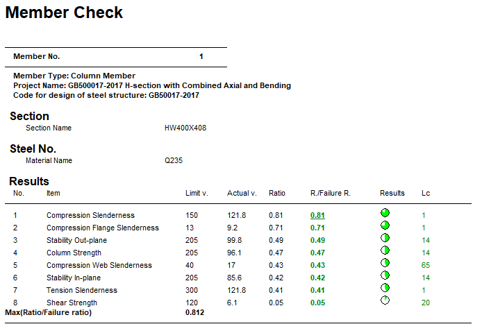
Comparison
| Result Type | Reference | STAAD.Pro | Difference | Comment |
|---|---|---|---|---|
| Column Strength | 0.47 | 0.47 | none | |
| In-plane Stability | 0.42 | 0.42 | none | |
| Out-plane Stability | 0.49 | 0.49 | none | |
| Compression Slenderness | 0.81 | 0.81 | none | |
| Tension Slenderness | 0.41 | 0.41 | none | |
| Shear Strength | 0.05 | 0.05 | none | |
| Flange Slenderness | 0.71 | 0.71 | none |
STAAD.Pro Input File
The file C:\Users\Public\Public Documents\STAAD.Pro 2023\Samples \Verification Models\09 Steel Design\China\GB500017-2017 H-section with Combined Axial and Bending.STD is typically installed with the program.
STAAD SPACE
START JOB INFORMATION
ENGINEER DATE 03-Aug-18
END JOB INFORMATION
INPUT WIDTH 79
UNIT METER KN
JOINT COORDINATES
1 0 0 0; 2 0 4.5 0; 3 0 9 0; 5 10 0 0; 6 10 4.5 0; 7 10 9 0; 17 0 0 6;
18 0 4.5 6; 19 0 9 6; 20 10 0 6; 21 10 4.5 6; 22 10 9 6; 23 2.5 4.5 6;
24 5 4.5 6; 25 7.5 4.5 6; 26 2.5 4.5 0; 27 5 4.5 0; 28 7.5 4.5 0; 29 2.5 9 0;
30 5 9 0; 31 7.5 9 0; 32 2.5 9 6; 33 5 9 6; 34 7.5 9 6;
MEMBER INCIDENCES
1 1 2; 2 2 3; 4 2 26; 5 3 29; 7 5 6; 8 6 7; 23 3 19; 24 6 21; 25 7 22;
30 17 18; 31 18 19; 32 18 23; 33 19 32; 34 20 21; 35 21 22; 36 23 24; 37 24 25;
38 25 21; 39 26 27; 40 27 28; 41 28 6; 42 29 30; 43 30 31; 44 31 7; 45 32 33;
46 33 34; 47 34 22; 48 23 26; 49 24 27; 50 25 28; 51 32 29; 52 33 30; 53 34 31;
DEFINE MATERIAL START
ISOTROPIC STEEL
E 2.05e+08
POISSON 0.3
DENSITY 76.8195
ALPHA 1.2e-05
DAMP 0.03
TYPE STEEL
STRENGTH FY 253200 FU 407800 RY 1.5 RT 1.2
END DEFINE MATERIAL
MEMBER PROPERTY CHINESE
1 2 7 8 30 31 34 35 TABLE ST HW400X408
4 5 32 33 36 TO 47 TABLE ST HN500X200
23 TO 25 48 TO 53 TABLE ST HN300X150
CONSTANTS
MATERIAL STEEL ALL
SUPPORTS
1 5 17 20 FIXED
DEFINE WIND LOAD
*{ TYPE AUTO, DON'T MODIFY FOLLOWING DATA
TYPE 2
INT 0.35 0.35 0.35 0.35 0.35 0.35 0.35 0.35 0.35 0.35 HEIG 0.9 1.8 2.7 3.6 -
4.5 5.4 6.3 7.2 8.1 9
*{ END MAIN TYPE
*{ END INCLINE TYPE
LOAD 1 LOADTYPE None  TITLE DL
SELFWEIGHT Y -1
MEMBER LOAD
23 TO 25 48 TO 53 UNI GY -12.5
LOAD 2 LOADTYPE None  TITLE LL
MEMBER LOAD
23 TO 25 48 TO 53 UMOM GY -10
LOAD 3 WL AUTO WIND LOAD
*{ THE FIRST AUTO BUILD WIND LOAD
*{ 自动定义的风荷载的类型号
*{ TYPE NO : 2 3 4 5 6 7 8 9 10 11 12 13 14 15 16 17
*{ 建筑结构的总高度
*{ STRUCTURE HIGH : 9
*{ 是否考虑风振系数的影响
*{ IS BETAZ : 0
*{ 建筑结构基本自振周期
*{ BASE PERIOD : 0.5
*{ 基本风压值
*{ BASE PRESS : 0.35
*{ 场地土粗造度类别
*{ SOIL TYPE : B
*{ 四个风向的迎风面宽度
*{ AWEATHER WIDTH : 6 6 10 10
*{ 四个风向的迎风面宽度
*{ AWEATHER WIDTH : 6 6 10 10
*{ 结构类型(空间或平面)
*{ STRUCTURE TYPE 2
*{ 风荷载体型系数,四个风向,四个面
*{ LEFTWIND MIUS : 0.8 -0.5 -0.6 -0.6
*{ RIGHTWIND MIUS : -0.5 0.8 -0.6 -0.6
*{ FRONTWIND MIUS : -0.6 -0.6 0.8 -0.5
*{ BACKWIND MIUS : -0.6 -0.6 -0.5 0.8
*{ 计算风压强度/高度曲线的方式
*{ INTENSITY FLAG : 1
*{ 用户指定需要计算风压强度的点数
*{ INTENSITY NUMBER : 10
*{ 等距离计算风压强度时的距离值
*{ INTENSITY ISOMETRY : 5
*{ 按照层高计算各点风压强度时的层高度
*{ INTENSITY FLOOR : 4.5
WIND LOAD X 0.8 TYPE 2
WIND LOAD -X 0.5 TYPE 2
WIND LOAD -Z 0.6 TYPE 2
WIND LOAD -Z -0.6 TYPE 2
LOAD 4 WR AUTO WIND LOAD
*{ AUTO BUILD WIND LOAD
WIND LOAD X -0.5 TYPE 2
WIND LOAD -X -0.8 TYPE 2
WIND LOAD -Z 0.6 TYPE 2
WIND LOAD -Z -0.6 TYPE 2
LOAD 5 WF AUTO WIND LOAD
*{ AUTO BUILD WIND LOAD
WIND LOAD -X -0.6 TYPE 2
WIND LOAD -X 0.6 TYPE 2
WIND LOAD -Z -0.8 TYPE 2
WIND LOAD Z -0.5 TYPE 2
LOAD 6 WB AUTO WIND LOAD
*{ AUTO BUILD WIND LOAD
WIND LOAD -X -0.6 TYPE 2
WIND LOAD -X 0.6 TYPE 2
WIND LOAD -Z 0.5 TYPE 2
WIND LOAD Z 0.8 TYPE 2
LOAD COMB 7 F : 1.20DL
1 1.2
LOAD COMB 8 F : 1.20DL+1.40LL
1 1.2 2 1.4
LOAD COMB 9 F : 1.20DL+0.84WL
1 1.2 3 0.84
LOAD COMB 10 F : 1.20DL+1.40LL+0.84WL
1 1.2 2 1.4 3 0.84
LOAD COMB 11 F : 1.20DL+0.84WR
1 1.2 4 0.84
LOAD COMB 12 F : 1.20DL+1.40LL+0.84WR
1 1.2 2 1.4 4 0.84
LOAD COMB 13 F : 1.20DL+0.84WF
1 1.2 5 0.84
LOAD COMB 14 F : 1.20DL+1.40LL+0.84WF
1 1.2 2 1.4 5 0.84
LOAD COMB 15 F : 1.20DL+0.84WB
1 1.2 6 0.84
LOAD COMB 16 F : 1.20DL+1.40LL+0.84WB
1 1.2 2 1.4 6 0.84
LOAD COMB 17 F : 1.00DL
1 1.0
LOAD COMB 18 F : 1.00DL+1.40LL
1 1.0 2 1.4
LOAD COMB 19 F : 1.00DL+0.84WL
1 1.0 3 0.84
LOAD COMB 20 F : 1.00DL+1.40LL+0.84WL
1 1.0 2 1.4 3 0.84
LOAD COMB 21 F : 1.00DL+0.84WR
1 1.0 4 0.84
LOAD COMB 22 F : 1.00DL+1.40LL+0.84WR
1 1.0 2 1.4 4 0.84
LOAD COMB 23 F : 1.00DL+0.84WF
1 1.0 5 0.84
LOAD COMB 24 F : 1.00DL+1.40LL+0.84WF
1 1.0 2 1.4 5 0.84
LOAD COMB 25 F : 1.00DL+0.84WB
1 1.0 6 0.84
LOAD COMB 26 F : 1.00DL+1.40LL+0.84WB
1 1.0 2 1.4 6 0.84
LOAD COMB 27 F : 1.20DL+0.98LL
1 1.2 2 0.98
LOAD COMB 28 F : 1.20DL+0.98LL+0.84WL
1 1.2 2 0.98 3 0.84
LOAD COMB 29 F : 1.20DL+0.98LL+0.84WR
1 1.2 2 0.98 4 0.84
LOAD COMB 30 F : 1.20DL+0.98LL+0.84WF
1 1.2 2 0.98 5 0.84
LOAD COMB 31 F : 1.20DL+0.98LL+0.84WB
1 1.2 2 0.98 6 0.84
LOAD COMB 32 F : 1.00DL+0.98LL
1 1.0 2 0.98
LOAD COMB 33 F : 1.00DL+0.98LL+0.84WL
1 1.0 2 0.98 3 0.84
LOAD COMB 34 F : 1.00DL+0.98LL+0.84WR
1 1.0 2 0.98 4 0.84
LOAD COMB 35 F : 1.00DL+0.98LL+0.84WF
1 1.0 2 0.98 5 0.84
LOAD COMB 36 F : 1.00DL+0.98LL+0.84WB
1 1.0 2 0.98 6 0.84
LOAD COMB 37 F : 1.20DL+1.40WL
1 1.2 3 1.4
LOAD COMB 38 F : 1.20DL+0.98LL+1.40WL
1 1.2 2 0.98 3 1.4
LOAD COMB 39 F : 1.20DL+1.40WR
1 1.2 4 1.4
LOAD COMB 40 F : 1.20DL+0.98LL+1.40WR
1 1.2 2 0.98 4 1.4
LOAD COMB 41 F : 1.20DL+1.40WF
1 1.2 5 1.4
LOAD COMB 42 F : 1.20DL+0.98LL+1.40WF
1 1.2 2 0.98 5 1.4
LOAD COMB 43 F : 1.20DL+1.40WB
1 1.2 6 1.4
LOAD COMB 44 F : 1.20DL+0.98LL+1.40WB
1 1.2 2 0.98 6 1.4
LOAD COMB 45 F : 1.00DL+1.40WL
1 1.0 3 1.4
LOAD COMB 46 F : 1.00DL+0.98LL+1.40WL
1 1.0 2 0.98 3 1.4
LOAD COMB 47 F : 1.00DL+1.40WR
1 1.0 4 1.4
LOAD COMB 48 F : 1.00DL+0.98LL+1.40WR
1 1.0 2 0.98 4 1.4
LOAD COMB 49 F : 1.00DL+1.40WF
1 1.0 5 1.4
LOAD COMB 50 F : 1.00DL+0.98LL+1.40WF
1 1.0 2 0.98 5 1.4
LOAD COMB 51 F : 1.00DL+1.40WB
1 1.0 6 1.4
LOAD COMB 52 F : 1.00DL+0.98LL+1.40WB
1 1.0 2 0.98 6 1.4
LOAD COMB 53 F : 1.35DL
1 1.35
LOAD COMB 54 F : 1.35DL+0.98LL
1 1.35 2 0.98
LOAD COMB 55 F : 1.35DL+0.84WL
1 1.35 3 0.84
LOAD COMB 56 F : 1.35DL+0.98LL+0.84WL
1 1.35 2 0.98 3 0.84
LOAD COMB 57 F : 1.35DL+0.84WR
1 1.35 4 0.84
LOAD COMB 58 F : 1.35DL+0.98LL+0.84WR
1 1.35 2 0.98 4 0.84
LOAD COMB 59 F : 1.35DL+0.84WF
1 1.35 5 0.84
LOAD COMB 60 F : 1.35DL+0.98LL+0.84WF
1 1.35 2 0.98 5 0.84
LOAD COMB 61 F : 1.35DL+0.84WB
1 1.35 6 0.84
LOAD COMB 62 F : 1.35DL+0.98LL+0.84WB
1 1.35 2 0.98 6 0.84
LOAD COMB 63 D : 1.00DL
1 1.0
LOAD COMB 64 D : 1.00DL+1.00LL
1 1.0 2 1.0
LOAD COMB 65 D : 1.00DL+0.60WL
1 1.0 3 0.6
LOAD COMB 66 D : 1.00DL+1.00LL+0.60WL
1 1.0 2 1.0 3 0.6
LOAD COMB 67 D : 1.00DL+0.60WR
1 1.0 4 0.6
LOAD COMB 68 D : 1.00DL+1.00LL+0.60WR
1 1.0 2 1.0 4 0.6
LOAD COMB 69 D : 1.00DL+0.60WF
1 1.0 5 0.6
LOAD COMB 70 D : 1.00DL+1.00LL+0.60WF
1 1.0 2 1.0 5 0.6
LOAD COMB 71 D : 1.00DL+0.60WB
1 1.0 6 0.6
LOAD COMB 72 D : 1.00DL+1.00LL+0.60WB
1 1.0 2 1.0 6 0.6
LOAD COMB 73 D : 1.00DL+0.70LL
1 1.0 2 0.7
LOAD COMB 74 D : 1.00DL+0.70LL+0.60WL
1 1.0 2 0.7 3 0.6
LOAD COMB 75 D : 1.00DL+0.70LL+0.60WR
1 1.0 2 0.7 4 0.6
LOAD COMB 76 D : 1.00DL+0.70LL+0.60WF
1 1.0 2 0.7 5 0.6
LOAD COMB 77 D : 1.00DL+0.70LL+0.60WB
1 1.0 2 0.7 6 0.6
LOAD COMB 78 D : 1.00DL+1.00WL
1 1.0 3 1.0
LOAD COMB 79 D : 1.00DL+0.70LL+1.00WL
1 1.0 2 0.7 3 1.0
LOAD COMB 80 D : 1.00DL+1.00WR
1 1.0 4 1.0
LOAD COMB 81 D : 1.00DL+0.70LL+1.00WR
1 1.0 2 0.7 4 1.0
LOAD COMB 82 D : 1.00DL+1.00WF
1 1.0 5 1.0
LOAD COMB 83 D : 1.00DL+0.70LL+1.00WF
1 1.0 2 0.7 5 1.0
LOAD COMB 84 D : 1.00DL+1.00WB
1 1.0 6 1.0
LOAD COMB 85 D : 1.00DL+0.70LL+1.00WB
1 1.0 2 0.7 6 1.0
PERFORM ANALYSIS
FINISHChinese steel design parameters (.gsp file):
[version=2207]
*{ The below data is for code check general information, please do not modify it.
[CodeCheck]
SeismicGrade=None
BeamBendingStrength=1
BeamShearStrength=1
BeamEquivalentStress=1
BeamOverallStability=1
BeamSlendernessWeb=1
BeamSlendernessFlange=1
TrussStrength=1
TrussStability=1
TrussShearStrength=1
ColumnStrength=1
ColumnStabilityMzMy=1
ColumnStabilityMyMz=1
PressedTrussSlenderness=1
TensionTrussSlenderness=1
ColumnSlendernessFlange=1
ColumnSlendernessWeb=1
BeamDeflection=1
SelectAll=0
GroupOptimize=0
FastOptimize=0
Iteration=0
SecondaryMembers=
SectCollectionOrder=0
[CheckOptionAngle]
PrimaryAxis=60.000000
SecondaryAxis=60.000000
ExtendLine=10.000000
*{ The above data is for code check general information, please do not modify it.

[GROUP=1]
Name(Parameter Name)=MAINBEAM
Type(Member Type)=1
Principle(Principle Rules)=0
SteelNo()=Q235
SectionSlendernessRatioGrade(Section Slenderness Ratio Grade)=3
Fatigue(Fatigue Calculation)=0
Optimization(Perform optimized design)=0
MaxFailure(Failure Ratio)=1
MinTooSafe(Safety Ratio)=0.3
CheckLoadCase(Force Loads Case No.)=ALL
CheckDispLoadCase(Displacement Loads Case No.)=63 To 85
BeamBendingStrength()=1
BeamShearStrength()=1
BeamEquivalentStress()=1
BeamOverallStability()=1
BeamSlendernessFlange(b/t on beam)=1
BeamSlendernessWeb(h0/tw on beam)=1
TrussStrength(Axial Force Strength)=1
SecondaryMoment(Secondary Moment of Truss)=0
TrussStability(Solid-web Axial Compression Stability)=1
TrussShearStrength(Axial Shear Strength)=1
PressedTrussSlenderness(Pressed Member Slenderness)=1
TensionTrussSlenderness(Tension Member Slenderness)=1
ColumnStrength(Column Member Strength)=1
ColumnStabilityMzMy(Column Stability In-plane)=1
ColumnStabilityMyMz(Column Stability Out-plane)=1
ColumnSlendernessFlange(b/t on column)=1
ColumnSlendernessWeb(h0/tw on column)=1
CheckItemAPPENDIX_B11(Beam Deflection)=1
UseAntiSeismic(Use Seismic Adjusting Factor)=0
GamaReStr(Seismic Adjusting Factor of Load-bearing Capacity for Strength)=0
GamaReSta(Seismic Adjusting Factor of Load-bearing Capacity for Stability)=0
SLevel(Grade of Seismic Resistance)=0
lmdc(Slenderness Limit of Compression Member)=0
lmdt(Slenderness Limit of Tension Member)=0
Lmd831(Slenderness of Seismic Column)=0
Lmd841(Slenderness of Seismic Brace)=0
Lmd9213(Slenderness of Seismic Single-story Plant)=0
LmdH28(Slenderness of Seismic Multi-story Plant)=0
rz(Plastic Development Factor in Major Axis)=0
ry(Plastic Development Factor in Minor Axis)=0
gamaSharp(Plastic Development Factor of sharp side)=0
betamz(the equivalent moment factor in Major Axis plane)=0
betamy(the equivalent moment factor in Minor Axis plane)=0
betatz(the equivalent moment factor out Major Axis plane)=0
betaty(the equivalent moment factor out Minor Axis plane)=0
HasHorLoadZ(Has Horizontal Load in Z-Axis)=0
HasHorLoadY(Has Horizontal Load in Y-Axis)=0
DFF(Deflection Limit of Beam)=400
DJ1(Start Node Number in Major Axis)=0
DJ2(End Node Number in Major Axis)=0
Horizontal(Check for Deflection in Minor Axis)=0
Cantilever(Cantilever Member)=0
fabz(Overall Stability Factor in Major Axis of Bending Member)=0
faby(Overall Stability Factor in Minor Axis of Bending Member)=0
StressFeature(Select the Stress Feature to calulate stability factor of beam)=1
faz(Overall Stability Factor in Major Axis of Axial Compression Member=0
fay(Overall Stability Factor in Minor Axis of Axial Compression Member)=0
lz(Unbraced Length in Major Axis)=0
ly(Unbraced Length in Minor Axis)=0
miuz(Effective Length Factor for Column in Major Axis)=0
miuy(Effective Length Factor for Column in Minor Axis)=0
Lateral(Member in Frame Without Sidesway or not)=0
APZ(Gyration Radius Calculation as Z-Axis Parallel Leg)=0
rFlange(Limit Ratio of Width to Thickness for Flange)=0
rWeb(Limit Ratio of High to Thickness for Web)=0
BucklingStrength(Axis forced member bulking strength)=0
ZSectType(Section Type in Z-Axis)=0
YSectType(Section Type in Y-Axis)=0
HSectWebInTrussPlane(Web of H in Truss Plane)=0
rAn(Net Factor of Section Area)=1
rWnz(Net Factor of Resistance Moment in Z-Axis)=1
rWny(Net Factor of Resistance Moment in Y-Axis)=1
CapReduce(Seismic Reduction Factor of Load-bearing Capacity for Brace)=1
AngleReduce(Angle Strength Reduce)=0
LAglConSta(Connect Type of unequal single angle)=0
LAngleStrength(Reduction Factor of Angle Strength)=0
LAngleStability(Reduction Factor of Angle Stability)=0
rTrussSectReduce(Effective Factor of Axial Force Section)=1
Members(Member Number)=40