T.2 Specifying concrete design parameters
Concrete design parameters allow you to directly specify some of the terms used in the equations for concrete member design.
For example, the grade of concrete or the maximum size of reinforcing bar you want to use.
Note: This tutorial uses
the 2011 edition of the American Concrete Institute 318 specification for
design (ACI 318-11).
Details on the code parameters can be found in
D1.F.3
Design Parameters.
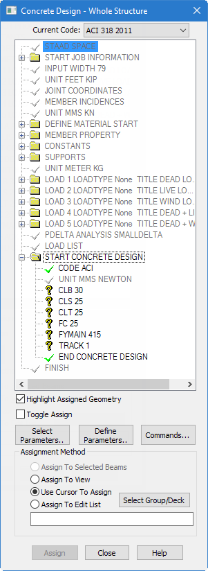
The STAAD input file commands generated are:
UNIT MMS NEWTON
CODE ACI
CLB 30 ALL
CLS 25 ALL
CLT 25 ALL
FC 25 ALL
FYMAIN 415 ALL
TRACK 1 ALL-
Set the force units as
Newton and the length units as
Millimeter.
Refer to T.2 Changing the input units of length for details.
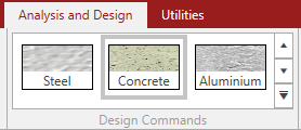
- On the Analysis and Design ribbon tab, select Concrete in the Design Commands gallery. The Concrete Design - Whole Structure dialog opens.
- On the Concrete Design - Whole Structure dialog, select ACI 318 2011 from the Current Code drop-down list.
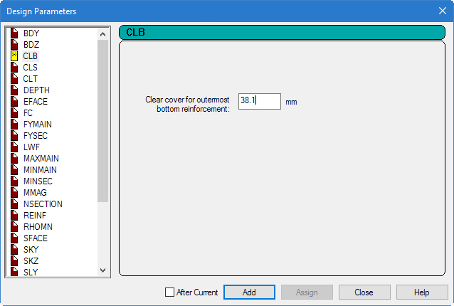
- Click Define Parameters in the Concrete Design dialog.
- Specify the clear cover on bottom:
- Repeat step 5 to define the remaining parameters:
-
Click
Close.
The Concrete Design dialog displays the parameters in the concrete design command.
-
Assign these parameters to all the members in the model:
- Select the first unassigned parameter in the Concrete Design | Whole Structure dialog.
- Select the Assign to View option.
-
Click
Assign.
A message dialog opens confirming you want to make this assignment.
- Click Yes.
- Repeat steps 8a though 8d for each unassigned parameter to assign them to all members.