G.5.2 Solid Elements
Solid elements enable the solution of structural problems involving general three dimensional stresses. There is a class of problems such as stress distribution in concrete dams or soil and rock strata where finite element analysis using solid elements provides a powerful tool.
Theoretical Basis
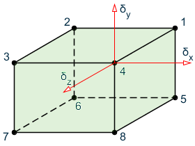
The solid element used in STAAD.Pro is of eight-noded, isoparametric type. These elements have three translational degrees-of-freedom per node.
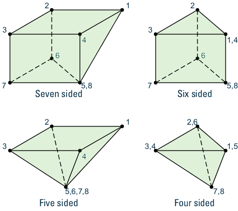
By collapsing various nodes together, an eight noded solid element can be degenerated to the following forms with four to seven nodes. Joints 1, 2, and 3 must be retained as a triangle.
The stiffness matrix of the solid element is evaluated by numerical integration with eight Gauss-Legendre points (2x2x2). The integration is the reduced second order to prevent shear locking. To facilitate the numerical integration, the geometry of the element is expressed by interpolating functions using the natural coordinate system, (r,s,t) of the element with its origin at the "center." The interpolating functions are shown below:
, ,
where| = | ||
| = |
The interpolation functions, hi are defined in the natural coordinate system, (r,s,t). Each of r,s and t varies between -1 and +1. The fundamental property of the unknown interpolation functions hi is that their values in natural coordinate system is unity at node, i, and zero at all other nodes of the element. The element displacements are also interpreted the same way as the geometry. For completeness, the functions are given below:
, ,
where u, v and w are displacements at any point in the element and ui,vi, wi, i=1,8 are corresponding nodal displacements in the coordinate system used to describe the geometry.
Three additional displacement "bubble" functions which have zero displacements at the surfaces are added in each direction for improved shear performance to form a 33x33 matrix. A modified integration is used for the bubble functions to make the results invariant with respect to element orientation (a one-point integration at the center is used).
Static condensation is used to reduce this matrix to a 24x24 matrix at the corner joints.
Local Coordinate System
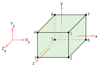
The local coordinate system used in solid element is the same as the global system.
Properties and Constants
Unlike members and shell (plate) elements, no properties are required for solid elements. However, the constants such as modulus of elasticity and Poisson’s ratio are to be specified. Also, density needs to be provided if selfweight is included in any load case.
Output of Element Stresses
Element stresses may be obtained at the center and at the joints of the solid element. The items that are printed are :
- Normal Stresses : SXX, SYY and SZZ
- Shear Stresses : SXY, SYZ and SZX
- Principal stresses : S1, S2 and S3
- Von Mises stresses:
Direction cosines : six direction cosines are printed, following the expression DC, corresponding to the first two principal stress directions.