D1.C.9 Composite Beam Design per the AISC LRFD 3rd edition code
The design of composite beams per the 3rd edition of the American LRFD code has been implemented. The salient points of this feature are as follows:
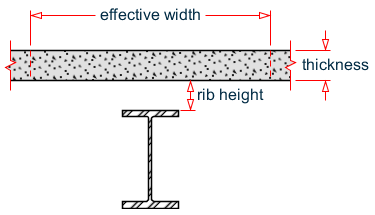
Nomenclature of composite beams
| = | ||
| = | ||
| = | ||
| = | ||
| = |
| Parameter Name | Default Value | Description |
|---|---|---|
| RBH | 0.0 in. | Rib height for steel form deck. |
| EFFW | Value used in analysis | Effective width of the slab. |
| FPC | Value used in analysis | Ultimate compressive strength of the concrete slab. |
Theoretical Basis
-
Find the maximum compressive force carried by concrete as:
0.85 fc⋅b⋅t
-
Find the maximum tensile force carried by the steel beam as:
As . fy
Tensile strength of concrete is ignored.
- If step 1 produces a higher value than step 2, plastic neutral axis (PNA) is in the slab. Else, it is in the steel beam.
Location of the Plastic Neutral Axis (PNA) defines the moment capacity:
-
Case 1: PNA in the slab
Find the depth of the PNA below the top of the slab as:
0.85fc⋅b⋅a = As⋅fy
Rearranging terms:
a = As⋅fy/(0.85fc⋅b)
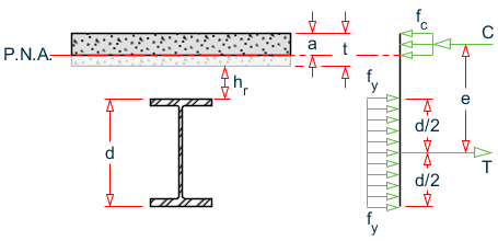
Plastic neutral axis in the concrete slab
Lever arm
e = d/2 + hr + t - a/2
Moment Capacity
ϕb(As⋅fy)e
-
Case 2: PNA in Steel Beam
whereCs + Cb = Tb - Cs
= - compressive force in slab = 0.85fc⋅b⋅t
- Cb
= - compressive force in steel beam
- Tb
= - tensile force in steel beam
Since the magnitude of Cb + |Tb| = As⋅fy
Substituting for Tb = (As⋅fy - Cb) gives:
Cs+ Cb = As⋅fy - Cb
Rearranging terms:
Cb= (As⋅fy - Cs)/2
Determine whether the PNA is within the top flange of the steel beam or inside the web:
where- Cf
= - maximum compressive force carried by the flange = Af⋅fy
- Af
= - area of the flange
If Cf ≥ Cb, the PNA lies within the flange (Case 2A)
If Cf < Cb, the PNA lies within the web (Case 2B)
-
Case 2A: PNA in Flange of Steel Beam
Calculate:
y = Cf/(bf⋅fy)
where- bf
= - width of the flange
The point of action of the tensile force is the centroid of the steel are below the PNA. After find that point, e1 and e2 can be calculated.
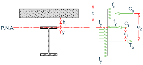
Plastic neutral axis falls within the top flange
Moment Capacity
ϕb(Cf⋅e1 + Cs⋅e2)
-
Case 2B: PNA in Web of Steel Beam
where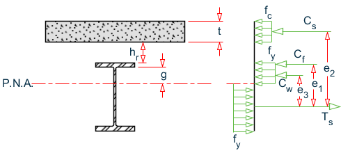
Plastic neutral axis falls within the web
- Cw
= - compressive force in the web = Cb - Cf
- g
= - Cw/(tw⋅fy)
- tw
= - thickness of the web
The point of action of the tensile force is the centroid of the steel area below the PNA. After finding that point, e1, e2, and e3 can be calculated.
Moment Capacity
ϕb(Cs⋅e2 + Cf⋅e1 + Cw⋅e3)
Utilization Ratio = Applied Moment / Moment Capacity
Notes
-
Rib Height is the distance from top of flange of steel beam to lower surface of concrete.
-
If the slab is flush on top of the steel beam, set the Rib Height to zero.
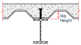
Steel deck form ribs
-
For moments which cause tension in the slab (called positive moments in STAAD.Pro convention), design of the beam is presently not carried out.
-
Shear connectors are presently not designed.
-
Member selection is presently not carried out.
-
In order to design a member as a composite beam, the member property specification during the analysis phase of the data must contain the CM attribute. See TR.20.1 レガシ鋼材テーブルからの特性の割り当て for details.