Designing members per a building code as specified
for this tutorial require you to provide values for some of the terms where the
default values do not match the problem requirements.
Note: This tutorial uses
the 2010 edition of the American Institute of Steel Construction 360
specification for design (AISC 360-10). Details on the code parameters can be
found in
Section 1 of the Design Codes section.
On the
Analysis and Design ribbon tab, select
Steel in the
Design Commands gallery.
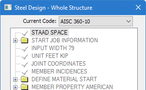
In the
Steel Design - Whole Structure
dialog, select
AISC 360-10 in the
Current Code list.
In the
Steel Design - Whole Structure
dialog, click
Define Parameters.
The
Design Parameters dialog opens.
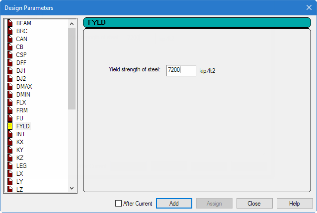
Specify the yield strength parameter:
Select the
FYLD parameter tab.
Type
7200 (kip/ft2) [50
(kip/in2)]in the
Yield strength of steel field.
Tip: This equates to a 50 ksi steel,
which is the common strength for American wide flange shapes. You can change
the input units before and after this command to use inches for convenience,
but this tutorial uses a non-standard unit here for brevity.
Click
Add.
The parameter list is added to the list of
commands in the
Steel Design - Whole Structure
dialog, including the selected design code and the yield strength value.
To define the remaining parameters, repeat step 4 except for
selecting the parameters and providing the values listed below.
Parameter
Value
TRACK
2 (select the option)
UNB
10 (ft) [120 (in)]
UNT
10 (ft) [120 (in)]
Click
Close in the Design Parameters
dialog.
Note: The steel design
parameters are all marked with an
icon. This indicates that they
need to be assigned to steel members.
Assign the yield strength to all members:
Select the
FYLD 7200 parameter in the command list.
Select the
Assign to View option in the Assignment
Method group.
Click
Assign.
A dialog opens confirming you want to
assign to the view (all members currently displayed in the view window).
Click
Yes.
Assign the output detail (TRACK) parameter to members 2 and 3:
Select the
TRACK 2 parameter in the command list.
Select the
Use Cursor to Assign option in the
Assignment Method group.
Click
Assign.
The mouse pointer changes to a
.
Click on each member in the Frame.
Click on
Assigning to stop assigning design
parameters.
Repeat step 8 to assign the other two parameters (UNB and UNT) to
members 2 and 3, as well.
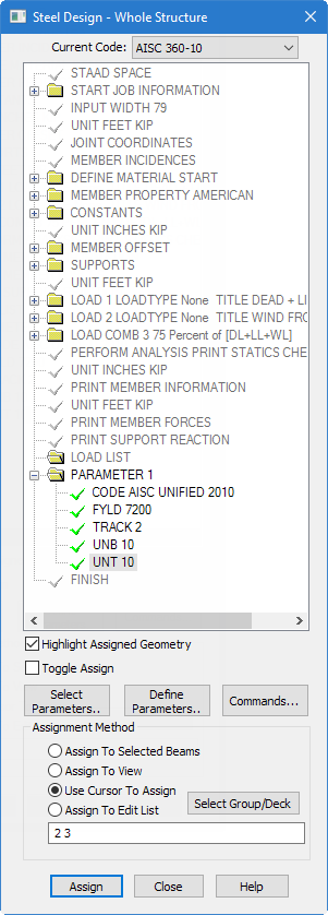
The
Steel Design - Whole Structure
dialog after the design parameters have been added and assigned
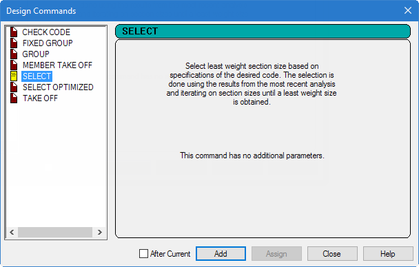
Add a command to instruct select sizes for members 2 and 3:
The select command is an instruction to the program
to assign the least-weight cross-section which satisfies all the code
requirements for the member.
In the
Steel Design - Whole Structure
dialog, click
Commands.
The
Design Commands dialog opens.
Select the
Select tab.
Click
Add.
Click
Close.
Assign the select command to members 2 and 3:
Select the
SELECT parameter in the command list.
Select the
Assign to Edit List option in the
Assignment Method group.
Type
2 3 in the list.
Notice this is a space-separated list of member numbers.
Click
Assign.
Tip: You
may also use either the method of selecting the members first or using the
cursor to assign the command to the members.
After the parameters are assigned, click anywhere in the
drawing area to deselect the members.
Tip: Remember to save your work by either
click
Save on the
File ribbon tab , the
Save tool, or pressing <CTRL+S>.
 icon. This indicates that they
need to be assigned to steel members.
icon. This indicates that they
need to be assigned to steel members.
 .
.