Used to apply nodal loads.
The following options are available under this tab:
Node
| Setting | Description |
|---|
|
Fx/Fx',
Fy/Fy',
Fz/Fz'
|
Type values of the forces in corresponding global
directions or inclined axis (') directions when the
Inclined Load? option is checked. A negative
sign (-) may be used.
|
|
Mx/Mx',
My/My',
Mz/Mz'
|
Type values of the moments about the corresponding
global directions or inclined axis (') directions when the
Inclined Load? option is checked. A negative
sign (-) may be used.
|
| Inclined Load?
|
Check this option to specify the load along an inclined
coordinate system. An inclined coordinate system is defined by an X' axis that
pass from the loaded joint through a reference point. That reference point can
be defined either a reference node, a set of absolute (global) coordinates, or
a set of relative distances from the loaded joint.
Note: When this option is checked, the load vector labels are
updated to reflect the inclined (') vector.
|
| Inclination
|
Select the option used to define the inclined coordinate system.
- Reference
Node - select an existing node number from the model. The global
coordinates of that node are displayed as read-only.
- Absolute - type
the global coordinates of an arbitrary point to use as the reference.
- Relative - type
relative distances from the loaded joint to the reference point. These
distances are measured along the global axes.
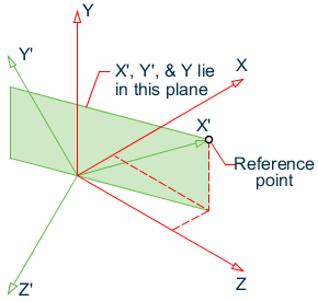
The reference point
–whether it is specified using absolute coordinates, relative distances, or a
reference joint– defines the direction of the x' axes from the loaded node to
the reference point. The direction of the Y' axes is then defined as the
direction perpendicular to x' that lies in the plane of X' and Y. In the
special case of when X' is in the direction of Y, Y' is taken to be the
direction of Z. The direction of Z' is then defined as the direction
perpendicular to the plane X' and Y' and follows the right-hand rule as for all
other axes systems used in
STAAD.Pro.
|
Support
Displacement
Used to specify a support displacement. Multiple support
displacements may be used for a single load case, but each support value and
direction must be entered independently.
| Setting | Description |
|---|
| Displacement
|
Specify the value of the displacement. A negative
sign (-) may be used.
|
| Direction
|
Select the direction of the displacement as
Fx,
Fy, or
Fz (translational), or
Mx,
My, or
Mz (rotational).
|
Region Node
Load
Used to specify a varying pressure at each joint on a plate or region.
This load item can be applied on joints directly whether they are plate corner nodes
or not.
| Setting | Description |
|---|
| Joint Load Data |
Choose Three Noded Facet or
Four Noded Facet, depending on whether the loaded
area is 3-noded or 4-noded. |
| Pressure Table |
Specify the corner node number and corresponding pressure load,
in the current units (displayed). |
| Direction |
The load may be applied along the Local Z
axis of an element or along one of the global X, Y, or Z axes
(GX, GY, or
GZ). |