TR.13.1 Plate and Shell Element Incidence Specification
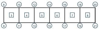
This set of commands is used to specify elements by defining the connectivity between joints. REPEAT and REPEAT ALL commands are available to facilitate generation of repetitive patterns.
The element incidences must be defined such that the model developed represents one single structure only, not two or more separate structures. STAAD.Pro is capable of detecting multiple structures automatically
General Format
ELEMENT INCIDENCES (SHELL)
i1 nA nB nC (nD) ( TO i2 i3 i4 )
REPEAT n ei ji
REPEAT ALL n ei ji
Description
ELEMENT INCIDENCES SHELL must be provided immediately after MEMBER INCIDENCES (if any) are specified.
| Parameter | Description |
|---|---|
| i1 | Element number (any number up to six digits). If MEMBER INCIDENCE is provided, this number must not coincide with any MEMBER number. |
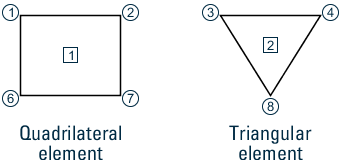
| nA … nD | Note: Refer to G.5.1 Plate and Shell Elements for additional
details on element incidences. Nodes nA
… nD correspond to IJKL
vertices.
Clockwise or counterclockwise node (i.e., joint) numbers
which represent the element connectivity. 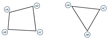
Element incidence |
The following parameters are needed if elements are to be generated:
| Parameter | Description |
|---|---|
| i2 | Last element number to which elements are generated. |
| i3 | Element number increment by which elements are generated. Defaults to 1 if omitted. |
| i4 | Joint number increment which will be added to incident joints. Defaults to 1 if omitted. |
The following data is needed if REPEAT or REPEAT ALL commands are used to generate elements:
| Parameter | Description |
|---|---|
| n | Number of times repeat is to be carried out. |
| ei | Element number increment. |
| ji | Joint number increment. |
The PRINT ELEMENT INFORMATION command may be used to verify the element incidences provided or generated by REPEAT and REPEAT ALL commands. Refer to Element Information for details.