V. AISI 2016 2CU F2F Compressive Strength
Verify the axial compressive strength of a double cold-formed channel section according to the AISI S100 2016 specification using both the LRFD and ASD methods.
Details
The member is 10 ft long cantilever. The section used is a pair of 600T125-54 channels in a front-to-front configuration (no spacing between channel toes).
Section Properties
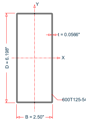
Properties of a 600T125-54 (listed as a 600CU125-54 in STAAD.Pro):
- Depth, D = 6.198 in
- Flange width, B = 1.250 in
- Thickness, t = 0.0566 in
- Inner radius, R = 0.0849 in.
- Cross-section area, A = 0.48 in2
- Moment of inertia about the Z axis, Iz = 2.34 in4
- Moment of inertia about the Y axis, Iy = 0.0539 in4
- Heel to C.G. distance, x = 0.204 in
- Torsional constant, J = 0.000513 in4
- Warping constant, Cw = 0.348 in6
Material Properties
- E = 29,000 ksi
- G = 11,200 ksi
- Fy = 36 ksi
- Fu = 58 ksi
Calculations
Section Properties
- Average radius, r = R + t/2 = 0.0849 + 0.0566 / 2 = 0.113 in.
- Clear depth of web, a = D = (2×r + t) = 6.198 - (2× 0.113 + 0.0566) = 5.915 in.
- Clear width of the flanges, b = B - (r + t/2) = 1.25 - (0.113 + 0.0556 / 2) = 1.109 in.
- Cross-section area, A = 2× 0.48 = 0.96 in2
- Moment of inertia about the Z axis, Iz = 2× 2.34 = 4.68 in4
- Moment of inertia about the Y axis, Iy = 2[0.0539 + 0.48×(1.25 - 0.204)2] = 1.158 in4
- Radius of gyration about the Z axis,
- Radius of gyration about the Y axis,
- Torsional constant, J = 2× 0.000513 = 0.00103 in4
- Center-to-center depth,
- Center-to-edge flange width,
- Warping constant, (Taken from Table 10.2, Case 4 of Reference 2; simplified for the case where h = 2×h1)
Compression Capacity for Yielding and Global Buckling
About the major axis:
The elastic flexural buckling stress
| (Eq. E2.1-1) |
| (Eq. E2-4) |
Since λcz < 1.5, the compressive strength is given by:
| (Eq. 2-2) |
About the minor axis:
The elastic flexural buckling stress
| (Eq. E2.1-1) |
| (Eq. E2-4) |
Since λcy < 1.5, the compressive strength is given by:
| (Eq. 2-2) |
The controlling compressive stress is the minimum of Fnz and Fny: Fn = 19.20 ksi
The nominal axial compressive strength, Pne = A × Fn = 0.96 × 19.20 = 18.43 kips
- LRFD: ϕcPne = 0.85 × 18.43 = 15.67 kips
- ASD: Pne/Ωc = 18.43 / 1.8 = 10.24 kips
Compression Capacity in Local Buckling
Global column stress about major axis (as defined in Section E2):
Fn = Fny = 19.20 ksi
Determine the effective area, Ae as per Appendix 1. The flanges of a front-to-front channel are considered stiffened elements.
Compression flange effective width:
| w = b = 1.109 in | (AISC Manual 3.3.2) |
| (E1. 1.1-4) |
| = | ||
| = |
The slenderness factor:
| (Eq. 1.1-3) |
As λ < 0.673, the local reduction factor, ρ = 1. Therefore, the effective width of the compression flange is bf = ρ×w = 1.109 in.
Web effective width:
| w = a = 5.915 in | (AISC Manual 3.3.2) |
Therefore, the effective width of the compression flange is bw = ρ×w = 0.597 × 5.915 = 3.532 in
The total effective area is the gross area minus the difference in nominal widths and effective widths:
Ae = A - 4×(b - bf)t - 2×(a - bw)t = 0.96 - 4×(1.109 - 1.109)×0.0566 - 2×(5.915 - 3.532)×0.0566 = 0.69 in.2
| (Eq. E3.1-1) |
- LRFD: ϕcPnℓ = 0.85 × 11.26 = kips
- ASD: Pnℓ/Ωc = 13.26 / 1.8 = 7.36 kips
Comparison
| Result Type | Reference | STAAD.Pro | Difference | Comments | |
|---|---|---|---|---|---|
| LRFD | Axial comp. per section E2 (kips) | 15.67 | 15.671 | negligible | |
| Local comp. per section E3 (kips) | 11.26 | 11.283 | negligible | ||
| ASD | Axial comp. per section E2 (kips) | 10.24 | 10.242 | negligible | |
| Local comp. per section E3 (kips) | 7.36 | 7.375 | negligible | ||
STAAD Input
The file C:\Users\Public\Public Documents\STAAD.Pro 2023\Samples \Verification Models\09 Steel Design\US\AISI\AISI 2016 2CU F2F Compressive Strength.STD is typically installed with the program.
- The material properties for design are specified by the parameters FYLD 36 and FU 58.
- A member with unreinforced webs is specified using TSA 0
STAAD SPACE
START JOB INFORMATION
ENGINEER DATE 11-Jan-22
ENGINEER NAME TK
END JOB INFORMATION
INPUT WIDTH 79
UNIT FEET KIP
JOINT COORDINATES
1 0 0 0; 2 10 0 0;
MEMBER INCIDENCES
1 1 2;
DEFINE MATERIAL START
ISOTROPIC STEEL
E 4.176e+06
POISSON 0.3
DENSITY 0.489024
ALPHA 6.5e-06
DAMP 0.03
G 1.6128e+06
TYPE STEEL
STRENGTH RY 1.5 RT 1.2
END DEFINE MATERIAL
UNIT INCHES KIP
MEMBER PROPERTY COLDFORMED AMERICAN
1 TABLE FR 600CU125-54
CONSTANTS
MATERIAL STEEL ALL
SUPPORTS
1 FIXED
LOAD 1 LOADTYPE None  TITLE LOAD CASE 1
JOINT LOAD
2 FX 10
PERFORM ANALYSIS
PARAMETER 1
CODE AISI 2016
METHOD LRFD
FYLD 36 ALL
FU 58 ALL
FLX 0 ALL
TSA 0 ALL
TRACK 2 ALL
CHECK CODE ALL
PARAMETER 2
CODE AISI 2016
METHOD ASD
FYLD 36 ALL
FU 58 ALL
FLX 0 ALL
TSA 0 ALL
TRACK 2 ALL
CHECK CODE ALL
FINISH
STAAD Output
            STAAD.Pro CODE CHECKING - (AISI S100-16) [LRFD] (v1.0)
           ********************************************************
ALL UNITS ARE IN "INCH" AND "KIP " (U.N.O.)
|-----------------------------------------------------------------------------|
|  MEMBER:     1     SECTION:FR  600CU125-54     LEN:  120.000     LOC:   0.000 |
| STATUS: PASS       RATIO:  0.322             REF: Sec. D2       LC:      1  |
|-----------------------------------------------------------------------------|
| DESIGN FORCES:                                                              |
|  Location:    0.000  Criteria:   Sec. D2              LC:           1       |
|  Fx:(T)      -10.000       Fy:        -0.000          Fz:      -0.000       |
|  Mx:           0.000       My:        -0.000          Mz:      -0.000       |
|-----------------------------------------------------------------------------|
| SECTION PROPERTIES:                                                         |
|  Ag:         0.96000       Az:     0.25096            Ay:     0.66958       |
|  Cz:         0.00000       Cy:     0.00000                                  |
|  Iz:         4.68000       Iy:     1.15815             J:     0.00104       |
|  Sz:         1.51016       Sy:     0.92652                                  |
|  Rz:         2.20794       Ry:     1.09837            Cw:     0.00000       |
|-----------------------------------------------------------------------------|
| MATERIAL INFO:                                                              |
|  Fy:    36.000        Fu:    58.000      E:  29000.000       G:  11200.000  |
|-----------------------------------------------------------------------------|
| DESIGN PROPERTIES:                                                          |
|  Member Length:   120.000   Lz:   120.000   Ly:   120.000   Lb:       0.000 |
| DESIGN PARAMETERS:                                                          |
|  Kz:   1.000    Ky:   1.000    NSF:  1.000                                  |
|-----------------------------------------------------------------------------|
| CRITICAL SLENDERNESS:                                                       |
|-----------------------------------------------------------------------------|
|  LC :     1   Actual :  109.253   Allowable :  300.000   Ratio :   0.364    |
|-----------------------------------------------------------------------------|
|  Section Dimension Check      |    Ratio     |    Limit     |     Status    |
|-----------------------------------------------------------------------------|
|  Radius To Thickness Ratio    |      1.500   |     10.000   |      PASS     |
|  Width To Thickness Ratio     |     17.085   |    500.000   |      PASS     |
|  Web Depth To Thickness Ratio |    104.505   |    200.000   |      PASS     |
|-----------------------------------------------------------------------------|
      STAAD SPACE                                              -- PAGE NO.    4
            STAAD.Pro CODE CHECKING - (AISI S100-16) [LRFD] (v1.0)
           ********************************************************
ALL UNITS ARE IN "INCH" AND "KIP " (U.N.O.)
|                                              - MEMBER:       1 (Contd.....) |
|                                                                             |
|-----------------------------------------------------------------------------|
| Limit States       | Load# |Location|  Demand  | Capacity |Ratio| Reference |
|--------------------|-------|--------|----------|----------|-----|-----------|
| Tension            |     1 |   0.00 |  -10.000 |   31.104 |0.322|Sec. D2    |
|   Yielding         |     1 |   0.00 |  -10.000 |   31.104 |0.322|Sec. D2    |
|   Rupture          |     1 |   0.00 |  -10.000 |   41.760 |0.239|Sec. D3    |
| Compression        |   -   |   -    |     -    |   11.283 |  -  |Sec. E3    |
|   Local Comp       |   -   |   -    |     -    |   11.283 |  -  |Sec. E3    |
|   Axial Comp       |   -   |   -    |     -    |   15.671 |  -  |Sec. E2    |
| Bending            |   -   |   -    |     -    |   14.721 |  -  |Sec. F2    |
|   Major Local Bend |   -   |   -    |     -    |   14.756 |  -  |Sec. F3    |
|   Minor Local Bend |   -   |   -    |     -    |   14.846 |  -  |Sec. F3    |
|   Major Sectional  |   -   |   -    |     -    |   48.929 |  -  |Sec. F2    |
|   Minor Sectional  |   -   |   -    |     -    |   30.019 |  -  |Sec. F2    |
|   LTB Major        |   -   |   -    |     -    |   14.721 |  -  |Sec. F2    |
|   LTB Minor        |   -   |   -    |     -    |   23.956 |  -  |Sec. F2    |
| Shear              |   -   |   -    |     -    |    5.150 |  -  |Sec. G2    |
|   Major Shear (Z)  |   -   |   -    |     -    |    5.150 |  -  |Sec. G2    |
|   Minor Shear (Y)  |   -   |   -    |     -    |    8.154 |  -  |Sec. G2    |
| Interaction        |     1 |   0.00 |     -    |     -    |0.322|Eq. H1.1-1 |
|   (Bend+Ten) Int1  |     1 |   0.00 |     -    |     -    |0.322|Eq. H1.1-1 |
|-----------------------------------------------------------------------------|
    43. PARAMETER 2
    44. CODE AISI 2016
    45. METHOD ASD
    46. FYLD 36 ALL
    47. FU 58 ALL
    48. FLX 0 ALL
    49. TSA 0 ALL
    50. TRACK 2 ALL
    51. CHECK CODE ALL
 STEEL DESIGN
   WARNING # 14 ~ Channel front to front member #     1 will be considered welded throughout length.
   Spacing will not be considered.
      STAAD SPACE                                              -- PAGE NO.    5
            STAAD.Pro CODE CHECKING - (AISI S100-16) [ASD ] (v1.0)
           ********************************************************
ALL UNITS ARE IN "INCH" AND "KIP " (U.N.O.)
|-----------------------------------------------------------------------------|
|  MEMBER:     1     SECTION:FR  600CU125-54     LEN:  120.000     LOC:   0.000 |
| STATUS: PASS       RATIO:  0.483             REF: Sec. D2       LC:      1  |
|-----------------------------------------------------------------------------|
| DESIGN FORCES:                                                              |
|  Location:    0.000  Criteria:   Sec. D2              LC:           1       |
|  Fx:(T)      -10.000       Fy:        -0.000          Fz:      -0.000       |
|  Mx:           0.000       My:        -0.000          Mz:      -0.000       |
|-----------------------------------------------------------------------------|
| SECTION PROPERTIES:                                                         |
|  Ag:         0.96000       Az:     0.25096            Ay:     0.66958       |
|  Cz:         0.00000       Cy:     0.00000                                  |
|  Iz:         4.68000       Iy:     1.15815             J:     0.00104       |
|  Sz:         1.51016       Sy:     0.92652                                  |
|  Rz:         2.20794       Ry:     1.09837            Cw:     0.00000       |
|-----------------------------------------------------------------------------|
| MATERIAL INFO:                                                              |
|  Fy:    36.000        Fu:    58.000      E:  29000.000       G:  11200.000  |
|-----------------------------------------------------------------------------|
| DESIGN PROPERTIES:                                                          |
|  Member Length:   120.000   Lz:   120.000   Ly:   120.000   Lb:       0.000 |
| DESIGN PARAMETERS:                                                          |
|  Kz:   1.000    Ky:   1.000    NSF:  1.000                                  |
|-----------------------------------------------------------------------------|
| CRITICAL SLENDERNESS:                                                       |
|-----------------------------------------------------------------------------|
|  LC :     1   Actual :  109.253   Allowable :  300.000   Ratio :   0.364    |
|-----------------------------------------------------------------------------|
|  Section Dimension Check      |    Ratio     |    Limit     |     Status    |
|-----------------------------------------------------------------------------|
|  Radius To Thickness Ratio    |      1.500   |     10.000   |      PASS     |
|  Width To Thickness Ratio     |     17.085   |    500.000   |      PASS     |
|  Web Depth To Thickness Ratio |    104.505   |    200.000   |      PASS     |
|-----------------------------------------------------------------------------|
      STAAD SPACE                                              -- PAGE NO.    6
            STAAD.Pro CODE CHECKING - (AISI S100-16) [ASD ] (v1.0)
           ********************************************************
ALL UNITS ARE IN "INCH" AND "KIP " (U.N.O.)
|                                              - MEMBER:       1 (Contd.....) |
|                                                                             |
|-----------------------------------------------------------------------------|
| Limit States       | Load# |Location|  Demand  | Capacity |Ratio| Reference |
|--------------------|-------|--------|----------|----------|-----|-----------|
| Tension            |     1 |   0.00 |  -10.000 |   20.695 |0.483|Sec. D2    |
|   Yielding         |     1 |   0.00 |  -10.000 |   20.695 |0.483|Sec. D2    |
|   Rupture          |     1 |   0.00 |  -10.000 |   27.840 |0.359|Sec. D3    |
| Compression        |   -   |   -    |     -    |    7.375 |  -  |Sec. E3    |
|   Local Comp       |   -   |   -    |     -    |    7.375 |  -  |Sec. E3    |
|   Axial Comp       |   -   |   -    |     -    |   10.242 |  -  |Sec. E2    |
| Bending            |   -   |   -    |     -    |    9.795 |  -  |Sec. F2    |
|   Major Local Bend |   -   |   -    |     -    |    9.818 |  -  |Sec. F3    |
|   Minor Local Bend |   -   |   -    |     -    |    9.878 |  -  |Sec. F3    |
|   Major Sectional  |   -   |   -    |     -    |   32.554 |  -  |Sec. F2    |
|   Minor Sectional  |   -   |   -    |     -    |   19.973 |  -  |Sec. F2    |
|   LTB Major        |   -   |   -    |     -    |    9.795 |  -  |Sec. F2    |
|   LTB Minor        |   -   |   -    |     -    |   15.939 |  -  |Sec. F2    |
| Shear              |   -   |   -    |     -    |    3.388 |  -  |Sec. G2    |
|   Major Shear (Z)  |   -   |   -    |     -    |    3.388 |  -  |Sec. G2    |
|   Minor Shear (Y)  |   -   |   -    |     -    |    5.364 |  -  |Sec. G2    |
| Interaction        |     1 |   0.00 |     -    |     -    |0.483|Eq. H1.1-1 |
|   (Bend+Ten) Int1  |     1 |   0.00 |     -    |     -    |0.483|Eq. H1.1-1 |
|-----------------------------------------------------------------------------|