V. ASCE 7 Geometric Irregularity
Verify geometric irregularity (reentrant corners in plan) check in accordance to the ASCE 7-16 specifications.
Details
A two story structure is modelled with diaphragms at the story levels.
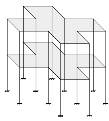
Isometric View
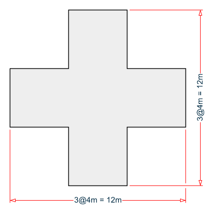
Plan View
Verification
Both diaphragms have the same dimensions and are doubly-symmetric. The overall building width in either direction is 12 m and the potential reentrant corner sides are 4 m. Therefore, the ratio of the A/L = 4 m / 12 m = 0.333 > 0.15.
Thus, each of the four corners are reentrant corners per the ASCE 7-16 code.
Results
| Result Type | Reference | STAAD.Pro | Difference | Comments |
|---|---|---|---|---|
| Node 1 | Reentrant | Reentrant | none | |
| Node 4 | Reentrant | Reentrant | none | |
| Node 7 | Reentrant | Reentrant | none | |
| Node 10 | Reentrant | Reentrant | none | |
| Node 25 | Reentrant | Reentrant | none | |
| Node 28 | Reentrant | Reentrant | none | |
| Node 31 | Reentrant | Reentrant | none | |
| Node 34 | Reentrant | Reentrant | none |
STAAD.Pro Input File
The file C:\Users\Public\Public Documents\STAAD.Pro 2023\Samples \Verification Models\06 Loading\IBC\IBC 2018 Geometric Irregularity.STD is typically installed with the program.
STAAD SPACE
START JOB INFORMATION
ENGINEER DATE 07-Mar-19
END JOB INFORMATION
INPUT WIDTH 79
UNIT METER KN
JOINT COORDINATES
1 3 0 0; 2 7 0 0; 3 7 0 4; 4 3 0 4; 5 3 0 -4; 6 -1 0 -4; 7 -1 0 0; 8 -5 0 0;
9 -5 0 4; 10 -1 0 4; 11 -1 0 8; 12 3 0 8; 13 3 -5 0; 14 7 -5 0; 15 7 -5 4;
16 3 -5 4; 17 3 -5 -4; 18 -1 -5 -4; 19 -1 -5 0; 20 -5 -5 0; 21 -5 -5 4;
22 -1 -5 4; 23 -1 -5 8; 24 3 -5 8; 25 3 5 0; 26 7 5 0; 27 7 5 4; 28 3 5 4;
29 3 5 -4; 30 -1 5 -4; 31 -1 5 0; 32 -5 5 0; 33 -5 5 4; 34 -1 5 4; 35 -1 5 8;
36 3 5 8;
MEMBER INCIDENCES
1 1 2; 2 2 3; 3 3 4; 4 1 5; 5 5 6; 6 6 7; 7 7 8; 8 8 9; 9 9 10; 10 10 11;
11 11 12; 12 12 4; 13 1 13; 14 2 14; 15 3 15; 16 4 16; 17 5 17; 18 6 18;
19 7 19; 20 8 20; 21 9 21; 22 10 22; 23 11 23; 24 12 24; 25 1 25; 26 2 26;
27 3 27; 28 4 28; 29 5 29; 30 6 30; 31 7 31; 32 8 32; 33 9 33; 34 10 34;
35 11 35; 36 12 36; 37 25 26; 38 26 27; 39 27 28; 40 25 29; 41 29 30; 42 30 31;
43 31 32; 44 32 33; 45 33 34; 46 34 35; 47 35 36; 48 36 28;
DEFINE MATERIAL START
ISOTROPIC CONCRETE
E 2.17185e+07
POISSON 0.17
DENSITY 23.5616
ALPHA 1e-05
DAMP 0.05
TYPE CONCRETE
STRENGTH FCU 27579
END DEFINE MATERIAL
MEMBER PROPERTY AMERICAN
1 TO 48 PRIS YD 0.5 ZD 0.5
CONSTANTS
MATERIAL CONCRETE ALL
SUPPORTS
13 TO 24 FIXED
MEMBER CRACKED
13 TO 36 REDUCTION RIY 0.7 RIZ 0.7
1 TO 12 37 TO 48 REDUCTION RIY 0.35 RIZ 0.35
DEFINE REFERENCE LOADS
LOAD R1 LOADTYPE Mass  TITLE REF LOAD CASE 1
SELFWEIGHT X 1
SELFWEIGHT Y 1
SELFWEIGHT Z 1
END DEFINE REFERENCE LOADS
FLOOR DIAPHRAGM
DIA 1 TYPE RIG HEI 0
DIA 2 TYPE RIG HEI 5
*CHECK IRREGULARITIES CODE IS1893 2016
CHECK IRREGULARITIES CODE ASCE7
DEFINE IBC 2018
ZIP 92887 I 1 RX 3 RZ 4 SCLASS 1 TL 8
LOAD 1 LOADTYPE None  TITLE STATIC_X
IBC LOAD X 1
LOAD 2 LOADTYPE None  TITLE STATIC_Z
IBC LOAD Z 1
PERFORM ANALYSIS PRINT LOAD DATA
PRINT ANALYSIS RESULTS
FINISH
STAAD.Pro Output
 -IRREGULARITY CHECKS
                    STAAD.PRO IRREGULARITIES CHECK - (  ASCE7-2016   )   v1.0
                    *********************************************************
 --TORSION IRREGULARITY CHECKS
 Torsion Irregularity Check
 Ref: Fig. C12.3-1 T1- Ratio Limit(s): 1.20, 1.40
 ------------------------------------------------
 Dia.   Extreme Points of Dia in X        Extreme Points of Dia in Z
       Node    Disp.    Node    Disp.    Node    Disp.     Node    Disp.
               (mm)             (mm)             (mm)              (mm)
 ------------------------------------------------------------------------
    1     12   0.07676      6   0.07676      2   0.07676      8   0.07676
    2     36   0.26545     30   0.26545     26   0.26545     32   0.26545
             Diaphragm  D X-max/avg  D Z-max/avg Status
             --------------------------------------
                   1     1.0000   1.0000        OK
                   2     1.0000   1.0000        OK
 --GEOMETRY IRREGULARITY CHECKS
 Re-Entrant Corner Check.
 (Ref: Fig. C12.3-1 T2- Ratio Limit: 0.15 )
 ------------------------------------------
     Node      Re-Entrant X-Proj  X-Proj/Lx Z-Proj  Z-Proj/Lz  Status
  Connectivilty    Node    ( m)              ( m)
 ----------------------------------------------------------------------
         2->         1      4.0000  0.3333    0.0000  0.0000 Re-Entrant
         5                  0.0000  0.0000    4.0000  0.3333
         6->         7      0.0000  0.0000    4.0000  0.3333 Re-Entrant
         8                  4.0000  0.3333    0.0000  0.0000
         9->        10      4.0000  0.3333    0.0000  0.0000 Re-Entrant
        11                  0.0000  0.0000    4.0000  0.3333
        12->         4      0.0000  0.0000    4.0000  0.3333 Re-Entrant
         3                  4.0000  0.3333    0.0000  0.0000
        26->        25      4.0000  0.3333    0.0000  0.0000 Re-Entrant
        29                  0.0000  0.0000    4.0000  0.3333
        30->        31      0.0000  0.0000    4.0000  0.3333 Re-Entrant
        32                  4.0000  0.3333    0.0000  0.0000
        33->        34      4.0000  0.3333    0.0000  0.0000 Re-Entrant
        35                  0.0000  0.0000    4.0000  0.3333
        36->        28      0.0000  0.0000    4.0000  0.3333 Re-Entrant
        27                  4.0000  0.3333    0.0000  0.0000
                   Diaphragm:    Lx:       Lz:
                                 ( m)     ( m)
                   ----------------------------
                        1     12.0000   12.0000
                        2     12.0000   12.0000
 --MASS IRREGULARITY CHECKS
 Mass Irregularity Check
 Ref: Fig. C12.3-2 T2- Ratio Limit: 1.50
 ---------------------------------------
 Dia.   Level     Mass       Above      Below     Ratio  Ratio  Status
        ( m)      ( kN)      ( kN)      ( kN)     Above  Below
 ---------------------------------------------------------------------
    1     0.000    636.163    459.451    Base      1.385   N/A     OK
    2     5.000    459.451    Top        636.163    N/A   0.722    OK