M. To check for warped plates
A warped plate is defined as a four-noded plate whose nodes do not lie on the same plane. This tool detects such plates.
You can set the tolerance for warped plates by first setting the Tolerance for Warped Plate Element Detection value on the Options dialog Tolerance tab. Only plates whose angular deviation exceeds this tolerance value will be displayed.
- Select one or more plates in the model.
-
Select the tool in the Geometry Tools group on the Utilities ribbon tab.
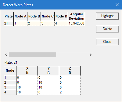
If any warped plates are detected, the Detect Warp Plates dialog opens. A list of all selected plates and their maximum angular deviation is displayed. The global coordinates for a selected plate are displayed below.
- (Optional) Click Highlight
- (Optional) Click Delete
- Click Close when you have completed reviewing warped plates.
An example of such an element is demonstrated in the following STAAD input.
STAAD SPACE
UNIT FEET KIP
JOINT COORDINATES
1 0 0 0; 2 0 10 0; 3 10 10 0; 4 10 0 2
ELEMENT INCIDENCES SHELL
21 1 2 3 4
FINISHNodes 1, 2, and 3 lie in the XY plane at Z = 0, but node 4 has a Z coordinate of 2, thereby causing the plate to become non-planar.
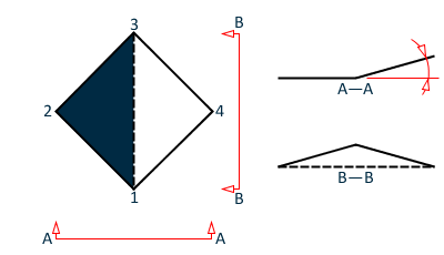
The warped plate check sub-divides the quad element into two sets of triangles: one with a diagonal from point 1 to point 3 and another diagonal from point 2 to point 4. These triangles do not lie in the same plane so an angle is formed between them at their shared edge. The largest angle between adjacent triangles in the warped quad element is compared against the tolerance threshold. If this tolerance angle is exceeded, then the plate is reported as excessively warped.