D1.F.6 Slab Design
Slab design is performed only for the moments MX and MY at the center of an element. Design will not be performed for SX, SY, SXY, SQX, SQY, or MXY. Also, design is not performed at any other point on the surface of the element.
A typical example of element design output is shown below. The reinforcement required to resist Mx moment is denoted as longitudinal reinforcement and the reinforcement required to resist My moment is denoted as transverse reinforcement ( D1.F.2 Section Types for Concrete Design). The parameters FYMAIN, FC, and CLEAR listed in D1.F.3 Design Parameters are relevant to slab design. Other parameters mentioned in Table 3.1 are not applicable to slab design. Please note that the default value of clear cover - parameters CLT and CLB - for plate elements is 0.75 inches, as shown in D1.F.3 Design Parameters.
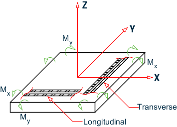
Sign convention of loaded plate element
Element design for flexure is done using the same rules that are used for beam design. A unit width (1 meter) is assumed as the width of the beam. This suits plate elements as MX and MY are in units of moment per unit width. Reinforcement is reported in units of mm2 per unit width. Longitudinal direction corresponds to the direction of reinforcement for MX, transverse corresponds to that for MY. Longitudinal reinforcement is the outer layer of reinforcement and transverse is the inner layer.
Elements are not designed for shear forces or axial stress.
Example Element Design Output
   ELEMENT DESIGN SUMMARY
   ----------------------

   ELEMENT    LONG. REINF      MOM-X /LOAD    TRANS. REINF      MOM-Y /LOAD
              (SQ.IN/FT)     (K-FT/FT)         (SQ.IN/FT)     (K-FT/FT)

        FY:    60.000 KSI FC:     4.000 KSI COVER (TOP):     0.750 IN
        COVER (BOTTOM):     0.750 IN TH:     6.000 IN
     47 TOP : Longitudinal direction - Only minimum steel required.
     47 TOP : Transverse direction   - Only minimum steel required.
     47 TOP :     0.130         0.00 /    0       0.130          0.00 /    0
        BOTT:     0.562        11.60 /    1       0.851         14.83 /    1