V. 2 Bay Frame Moments and Shear
To find the member forces in a 1x2 bay plane frame with members of rectangular section.
Problem
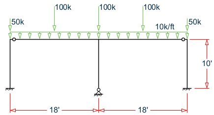
The frame supports a uniformly distributed load and concentrated loads. Calculate the bending moment and shear force at the mid point of the beam of the first bay.
E = 30,000 ksi
Columns are 12"×24", beams are 12"×30"
STAAD Input
The file C:\Users\Public\Public Documents\STAAD.Pro 2023\Samples \Verification Models\03 Frames\2 Bay Frame Moments and Shear.STD is typically installed with the program.
STAAD PLANE : 2 BAY FRAME MOMENTS AND SHEAR
START JOB INFORMATION
ENGINEER DATE 09-Oct-17
END JOB INFORMATION
*
*  REFERENCE: "MANUAL OF STEEL CONSTRUCTION-ALLOWABLE STRESS DESIGN",
*             AISC, CHICAGO, ILLINOIS, 1989.
*
UNIT FEET KIP
JOINT COORDINATES
1 0 0 0; 2 18 0 0; 3 36 0 0; 4 0 10 0; 5 18 10 0; 6 36 10 0;
MEMBER INCIDENCES
1 1 4; 2 2 5; 3 3 6; 4 4 5; 5 5 6;
UNIT INCHES KIP
MEMBER PROPERTY AMERICAN
1 TO 3 PRIS AX 1e+07 IZ 13824
4 5 PRIS AX 1e+07 IZ 27000
MEMBER RELEASE
5 END MZ
4 START MZ
SUPPORTS
1 3 FIXED
2 PINNED
DEFINE MATERIAL START
ISOTROPIC MATERIAL1
E 30000
POISSON 0.290909
END DEFINE MATERIAL
CONSTANTS
MATERIAL MATERIAL1 ALL
UNIT FEET KIP
LOAD 1 VERTICAL POINT LOADS
JOINT LOAD
4 6 FY -50
5 FY -100
MEMBER LOAD
4 CON GY -100 9
5 CON GY -100 9
LOAD 2 VERTICAL UNIFORM LOADS
MEMBER LOAD
4 UNI GY -10
5 UNI GY -10
PERFORM ANALYSIS
UNIT INCHES KIP
SECTION 0.501 MEMB 4
PRINT MEMBER SECTION FORCES LIST 4
FINISH