Member end forces and moments in the member result
from loads applied to the structure. These forces are in the local member
coordinate system. The following figures show the member end actions with their
directions.
Note: In addition to the member end forces, intermediate forces and section stresses are reported
at 13 equally spaced sections along each analytical member.
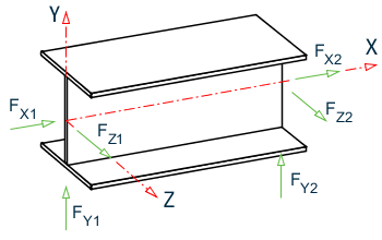
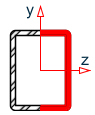
Member end forces
when Global Y is vertical

Member end moments
when Global Y is vertical
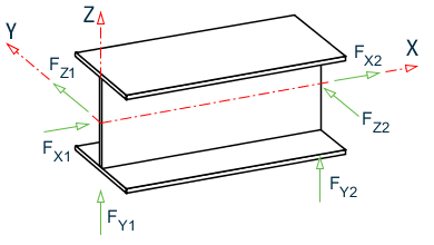
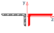
Member end forces
when Global Z is vertical (that is,
SET Z UP is specified)

Member end moments
when Global Z is vertical (that is,
SET Z UP is specified)
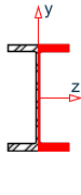
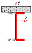
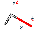
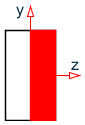
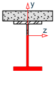
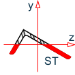
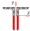
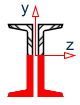
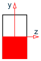
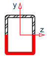
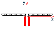
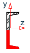
Stress Zones Due to
Bending
Note: Local X axis goes
into the page; Global Y is vertically upwards; Shaded area indicates zone under
compression; Non-shaded area indicates zone under tension
Note: Local X axis goes
into the page; Global Y is vertically upwards; Shaded area indicates zone under
compression; Non-shaded area indicates zone under tension.