EX. US-25 Analysis of a Structure with Compression-Only Members
This example demonstrates the usage of compression-only members. Since the structural condition is load dependent, the PERFORM ANALYSIS command is specified once for each primary load case.
This problem is installed with the program by default to C:\Users\Public\Public Documents\STAAD.Pro CONNECT Edition\Samples\Sample Models\US\US-25 Analysis of a Structure with Compression-Only Members.STD when you install the program.
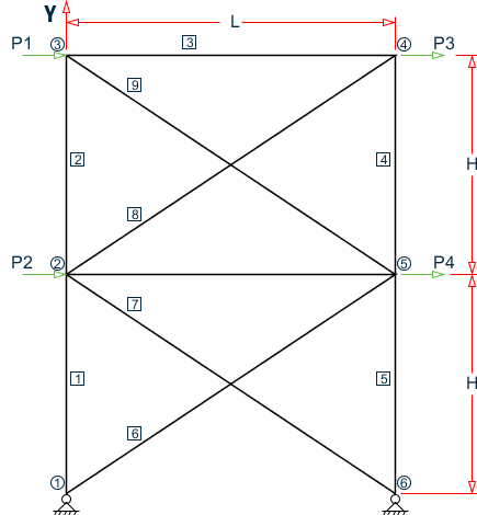
This example has been created to illustrate the command specification for a structure with certain members capable of carrying compressive force only. It is important to note that the analysis can be done for only 1 load case at a time. This is because, the set of "active" members (and hence the stiffness matrix) is load case dependent.
- L = 15 ft, H = 10 ft
- Load case 1: P1 = 10 kips & P2 = 15 kips
- Load case 2: P3 = -10 kips & P4 = -15 kips
    STAAD PLANE
    * EXAMPLE FOR COMPRESSION-ONLY MEMBERS
The input data is initiated with the word STAAD. This structure is a PLANE frame. The second line is an optional comment line.
UNIT FEET KIP
Units for the commands to follow are specified above.
    JOINT COORDINATES
    1 0 0 ; 2 0 10 ; 3 0 20 ; 4 15 20 ; 5 15 10 ; 6 15 0
Joint coordinates of joints 1 to 6 are defined above.
    MEMBER INCIDENCES
    1 1 2 5 ; 6 1 5 ; 7 2 6 ; 8 2 4 ; 9 3 5 ; 10 2 5
The members 1 to 10 are defined along with the joints to which they are connected.
    MEMBER COMPRESSION
    6 TO 9
Members 6 to 9 are defined as COMPRESSION-only members. Hence for each load case, if during the analysis, any of the members 6 to 9 is found to be carrying a tensile force, it is disabled from the structure and the analysis is carried out again with the modified structure.
    MEMBER PROPERTY AMERICAN
    1 TO 10 TA ST W12X26
Properties for members 1 to 10 are defined as the STandard W12X26 section from the American AISC steel table.
    MEMBER PROPERTY BRITISH
    1 TO 10 TA ST UC152X152X30
    DEFINE MATERIAL START
    ISOTROPIC STEEL
    E 29000
    POISSON 0.3
    DENSITY 283e-006
    ALPHA 6e-006
    DAMP 0.03
    TYPE STEEL
    STRENGTH FY 36 FU 58 RY 1.5 RT 1.2
    END DEFINE MATERIAL
    CONSTANT
    MATERIAL STEEL ALL
The DEFINE MATERIAL command is used to specify material properties and the CONSTANT is used to assign the material to all members.
    SUPPORT
    1 6 PINNED
Joints 1 and 6 are declared as pinned-supported.
    LOAD 1
    JOINT LOAD
    2 FX 15
    3 FX 10
Load 1 is defined above and consists of joint loads in the global X direction at joints 2 and 3.
PERFORM ANALYSIS
The above structure is analyzed for load case 1.
    CHANGE
    MEMBER COMPRESSION
    6 TO 9
One or more among the members 6 to 9 may have been in-activated in the previous analysis. The CHANGE command restores the original structure to prepare it for the analysis for the next primary load case. The members with the compression-only attribute are specified again.
In load case 2, joint loads are applied in the negative global X direction at joints 4 and 5.
PERFORM ANALYSIS
CHANGE
The instruction to analyze the structure is specified again. Next, any compression-only members that were inactivated during the second analysis (due to the fact that they were subjected to tensile axial forces) are re-activated with the CHANGE command. Without the re-activation, these members cannot be accessed for further processing.
LOAD 3
REPEAT LOAD
1 1.0 2 1.0
Load case 3 illustrates the technique employed to instruct STAAD to create a load case which consists of data to be assembled from other load cases already specified earlier. We would like the program to analyze the structure for loads from cases 1 and 2 acting simultaneously. In other words, the above instruction is the same as the following:
The analysis is carried out for load case 3.
CHANGE
The members inactivated during the analysis of load case 3 are re-activated for further processing.
LOAD LIST ALL
At the end of any analysis, only those load cases for which the analysis was done most recently, are recognized as the "active" load cases. The LOAD LIST ALL command enables all the load cases in the structure to be made active for further processing.
PRINT ANALYSIS RESULTS
The program is instructed to write the joint displacements, support reactions and member forces to the output file.
FINISH
The STAAD run is terminated.
Input File
STAAD PLANE EXAMPLE FOR COMPRESSION-ONLY MEMBERS
UNIT FEET KIP
SET NL 3
JOINT COORDINATES
1 0 0 ; 2 0 10 ; 3 0 20 ; 4 15 20 ; 5 15 10 ; 6 15 0
MEMBER INCIDENCES
1 1 2 5
6 1 5 ; 7 2 6 ; 8 2 4 ; 9 3 5 ; 10 2 5
MEMBER COMPRESSION
6 TO 9
MEMBER PROPERTY AMERICAN
1 TO 10 TA ST W12X26
UNIT INCH
DEFINE MATERIAL START
ISOTROPIC STEEL
E 29000
POISSON 0.3
DENSITY 283e-006
ALPHA 6e-006
DAMP 0.03
TYPE STEEL
STRENGTH FY 36 FU 58 RY 1.5 RT 1.2
END DEFINE MATERIAL
CONSTANT
MATERIAL STEEL ALL
SUPPORT
1 6 PINNED
LOAD 1
JOINT LOAD
2 FX 15
3 FX 10
PERFORM ANALYSIS
CHANGE
MEMBER COMPRESSION
6 TO 9
    LOAD 2
    JOINT LOAD
    4 FX -10
    5 FX -15
    PERFORM ANALYSIS
    CHANGE
MEMBER COMPRESSION
6 TO 9
    LOAD 3
    REPEAT LOAD
    1 1.0 2 1.0
PERFORM ANALYSIS
CHANGE
LOAD LIST ALL
PRINT ANALYSIS RESULTS
FINISH
STAAD Output File
                                                                  PAGE NO.    1
             ****************************************************
             *                                                  *
             *           STAAD.Pro CONNECT Edition              *
             *           Version  22.12.00.***                  *
             *           Proprietary Program of                 *
             *           Bentley Systems, Inc.                  *
             *           Date=    OCT 27, 2022                  *
             *           Time=    15: 9:46                      *
             *                                                  *
             *  Licensed to: Bentley Systems Inc                *
             ****************************************************
     1. STAAD PLANE EXAMPLE FOR COMPRESSION-ONLY MEMBERS
INPUT FILE: US-25 Analysis of a Structure with Compression-Only Members.STD
     2. UNIT FEET KIP
     3. SET NL 3
     4. JOINT COORDINATES
     5. 1 0 0 ; 2 0 10 ; 3 0 20 ; 4 15 20 ; 5 15 10 ; 6 15 0
     6. MEMBER INCIDENCES
     7. 1 1 2 5
     8. 6 1 5 ; 7 2 6 ; 8 2 4 ; 9 3 5 ; 10 2 5
     9. MEMBER COMPRESSION
    10. 6 TO 9
    11. MEMBER PROPERTY AMERICAN
    12. 1 TO 10 TA ST W12X26
    13. UNIT INCH
    14. DEFINE MATERIAL START
    15. ISOTROPIC STEEL
    16. E 29000
    17. POISSON 0.3
    18. DENSITY 283E-006
    19. ALPHA 6E-006
    20. DAMP 0.03
    21. TYPE STEEL
    22. STRENGTH FY 36 FU 58 RY 1.5 RT 1.2
    23. END DEFINE MATERIAL
    24. CONSTANT
    25. MATERIAL STEEL ALL
    26. SUPPORT
    27. 1 6 PINNED
    28. LOAD 1
    29. JOINT LOAD
    30. 2 FX 15
    31. 3 FX 10
    32. PERFORM ANALYSIS
      EXAMPLE FOR COMPRESSION-ONLY MEMBERS                     -- PAGE NO.    2
            P R O B L E M   S T A T I S T I C S
            -----------------------------------
     NUMBER OF JOINTS          6  NUMBER OF MEMBERS      10
     NUMBER OF PLATES          0  NUMBER OF SOLIDS        0
     NUMBER OF SURFACES        0  NUMBER OF SUPPORTS      2
           Using 64-bit analysis engine.
           SOLVER USED IS THE IN-CORE ADVANCED MATH SOLVER
   TOTAL      PRIMARY LOAD CASES =     1, TOTAL DEGREES OF FREEDOM =      14
   TOTAL LOAD COMBINATION  CASES =     0  SO FAR.
*** LOAD CASE     1 -- START ITERATION NO.   2
  **NOTE-Tension/Compression converged after  2 iterations, Case=    1
    33. CHANGE
    34. MEMBER COMPRESSION
    35. 6 TO 9
    36. LOAD 2
    37. JOINT LOAD
    38. 4 FX -10
    39. 5 FX -15
    40. PERFORM ANALYSIS
*** LOAD CASE     2 -- START ITERATION NO.   2
  **NOTE-Tension/Compression converged after  2 iterations, Case=    2
    41. CHANGE
    42. MEMBER COMPRESSION
    43. 6 TO 9
    44. LOAD 3
    45. REPEAT LOAD
    46. 1 1.0 2 1.0
    47. PERFORM ANALYSIS
  **NOTE-Tension/Compression converged after  1 iterations, Case=    3
    48. CHANGE
      EXAMPLE FOR COMPRESSION-ONLY MEMBERS                     -- PAGE NO.    3
    49. LOAD LIST ALL
    50. PRINT ANALYSIS RESULTS
  ANALYSIS RESULTS
      EXAMPLE FOR COMPRESSION-ONLY MEMBERS                     -- PAGE NO.    4
   JOINT DISPLACEMENT (INCH RADIANS)    STRUCTURE TYPE = PLANE
   ------------------
 JOINT  LOAD   X-TRANS   Y-TRANS   Z-TRANS   X-ROTAN   Y-ROTAN   Z-ROTAN
      1    1    0.00000   0.00000   0.00000   0.00000   0.00000  -0.00041
           2    0.00000   0.00000   0.00000   0.00000   0.00000   0.00050
           3    0.00000   0.00000   0.00000   0.00000   0.00000  -0.00004
      2    1    0.04314   0.01262   0.00000   0.00000   0.00000  -0.00025
           2   -0.05088  -0.00373   0.00000   0.00000   0.00000   0.00024
           3    0.00364   0.00080   0.00000   0.00000   0.00000  -0.00001
      3    1    0.07775   0.01618   0.00000   0.00000   0.00000  -0.00022
           2   -0.07766  -0.00381   0.00000   0.00000   0.00000   0.00015
           3    0.00255   0.00215   0.00000   0.00000   0.00000   0.00001
      4    1    0.07766  -0.00381   0.00000   0.00000   0.00000  -0.00015
           2   -0.07775   0.01618   0.00000   0.00000   0.00000   0.00022
           3   -0.00255   0.00215   0.00000   0.00000   0.00000  -0.00001
      5    1    0.05088  -0.00373   0.00000   0.00000   0.00000  -0.00024
           2   -0.04314   0.01262   0.00000   0.00000   0.00000   0.00025
           3   -0.00364   0.00080   0.00000   0.00000   0.00000   0.00001
      6    1    0.00000   0.00000   0.00000   0.00000   0.00000  -0.00050
           2    0.00000   0.00000   0.00000   0.00000   0.00000   0.00041
           3    0.00000   0.00000   0.00000   0.00000   0.00000   0.00004
      EXAMPLE FOR COMPRESSION-ONLY MEMBERS                     -- PAGE NO.    5
   SUPPORT REACTIONS -UNIT KIP  INCH    STRUCTURE TYPE = PLANE
   -----------------
 JOINT  LOAD   FORCE-X   FORCE-Y   FORCE-Z     MOM-X     MOM-Y     MOM Z
      1    1     -0.13    -23.33      0.00      0.00      0.00      0.00
           2     24.87     23.33      0.00      0.00      0.00      0.00
           3      2.18      0.00      0.00      0.00      0.00      0.00
      6    1    -24.87     23.33      0.00      0.00      0.00      0.00
           2      0.13    -23.33      0.00      0.00      0.00      0.00
           3     -2.18      0.00      0.00      0.00      0.00      0.00
      EXAMPLE FOR COMPRESSION-ONLY MEMBERS                     -- PAGE NO.    6
   MEMBER END FORCES    STRUCTURE TYPE = PLANE
   -----------------
   ALL UNITS ARE -- KIP  INCH     (LOCAL )
  MEMBER  LOAD  JT     AXIAL   SHEAR-Y  SHEAR-Z   TORSION     MOM-Y      MOM-Z
      1    1     1    -23.33      0.13     0.00      0.00      0.00       0.00
                 2     23.33     -0.13     0.00      0.00      0.00      15.87
           2     1      6.90     -0.22     0.00      0.00      0.00      -0.00
                 2     -6.90      0.22     0.00      0.00      0.00     -25.90
           3     1     -1.47      0.03     0.00      0.00      0.00       0.00
                 2      1.47     -0.03     0.00      0.00      0.00       3.24
      2    1     2     -6.58      0.24     0.00      0.00      0.00      12.72
                 3      6.58     -0.24     0.00      0.00      0.00      15.70
           2     2      0.15     -0.11     0.00      0.00      0.00      -2.32
                 3     -0.15      0.11     0.00      0.00      0.00     -11.30
           3     2     -2.50     -0.03     0.00      0.00      0.00      -2.74
                 3      2.50      0.03     0.00      0.00      0.00      -0.79
      3    1     3      0.11     -0.15     0.00      0.00      0.00     -15.70
                 4     -0.11      0.15     0.00      0.00      0.00     -11.30
           2     3      0.11      0.15     0.00      0.00      0.00      11.30
                 4     -0.11     -0.15     0.00      0.00      0.00      15.70
           3     3      6.28      0.00     0.00      0.00      0.00       0.79
                 4     -6.28     -0.00     0.00      0.00      0.00      -0.79
      4    1     4      0.15      0.11     0.00      0.00      0.00      11.30
                 5     -0.15     -0.11     0.00      0.00      0.00       2.32
           2     4     -6.58     -0.24     0.00      0.00      0.00     -15.70
                 5      6.58      0.24     0.00      0.00      0.00     -12.72
           3     4     -2.50      0.03     0.00      0.00      0.00       0.79
                 5      2.50     -0.03     0.00      0.00      0.00       2.74
      5    1     5      6.90      0.22     0.00      0.00      0.00      25.90
                 6     -6.90     -0.22     0.00      0.00      0.00       0.00
           2     5    -23.33     -0.13     0.00      0.00      0.00     -15.87
                 6     23.33      0.13     0.00      0.00      0.00       0.00
           3     5     -1.47     -0.03     0.00      0.00      0.00      -3.24
                 6      1.47      0.03     0.00      0.00      0.00       0.00
      6    1     1      0.00      0.00     0.00      0.00      0.00       0.00
                 5      0.00      0.00     0.00      0.00      0.00       0.00
           2     1     29.63      0.00     0.00      0.00      0.00       0.00
                 5    -29.63      0.00     0.00      0.00      0.00       0.00
           3     1      2.66      0.00     0.00      0.00      0.00       0.00
                 5     -2.66      0.00     0.00      0.00      0.00       0.00
      7    1     2     29.63      0.00     0.00      0.00      0.00       0.00
                 6    -29.63      0.00     0.00      0.00      0.00       0.00
      EXAMPLE FOR COMPRESSION-ONLY MEMBERS                     -- PAGE NO.    7
   MEMBER END FORCES    STRUCTURE TYPE = PLANE
   -----------------
   ALL UNITS ARE -- KIP  INCH     (LOCAL )
  MEMBER  LOAD  JT     AXIAL   SHEAR-Y  SHEAR-Z   TORSION     MOM-Y      MOM-Z
           2     2      0.00      0.00     0.00      0.00      0.00       0.00
                 6      0.00      0.00     0.00      0.00      0.00       0.00
           3     2      2.66      0.00     0.00      0.00      0.00       0.00
                 6     -2.66      0.00     0.00      0.00      0.00       0.00
      8    1     2      0.00      0.00     0.00      0.00      0.00       0.00
                 4      0.00      0.00     0.00      0.00      0.00       0.00
           2     2     11.60      0.00     0.00      0.00      0.00       0.00
                 4    -11.60      0.00     0.00      0.00      0.00       0.00
           3     2      4.51      0.00     0.00      0.00      0.00       0.00
                 4     -4.51      0.00     0.00      0.00      0.00       0.00
      9    1     3     11.60      0.00     0.00      0.00      0.00       0.00
                 5    -11.60      0.00     0.00      0.00      0.00       0.00
           2     3      0.00      0.00     0.00      0.00      0.00       0.00
                 5      0.00      0.00     0.00      0.00      0.00       0.00
           3     3      4.51      0.00     0.00      0.00      0.00       0.00
                 5     -4.51      0.00     0.00      0.00      0.00       0.00
     10    1     2     -9.55     -0.32     0.00      0.00      0.00     -28.60
                 5      9.55      0.32     0.00      0.00      0.00     -28.21
           2     2     -9.55      0.32     0.00      0.00      0.00      28.21
                 5      9.55     -0.32     0.00      0.00      0.00      28.60
           3     2      8.98     -0.00     0.00      0.00      0.00      -0.50
                 5     -8.98      0.00     0.00      0.00      0.00       0.50
   ************** END OF LATEST ANALYSIS RESULT **************
    51. FINISH
      EXAMPLE FOR COMPRESSION-ONLY MEMBERS                     -- PAGE NO.    8
             *********** END OF THE STAAD.Pro RUN ***********
               **** DATE= OCT 27,2022   TIME= 15: 9:47 ****
         ************************************************************
         *   For technical assistance on STAAD.Pro, please visit    *
         *   http://www.bentley.com/en/support/                     *
         *                                                          *
         *   Details about additional assistance from               *
         *   Bentley and Partners can be found at program menu      *
         *   Help->Technical Support                                *
         *                                                          *
         *           Copyright (c) Bentley Systems, Inc.            *
         *                http://www.bentley.com                    *
         ************************************************************