EX. US-7 Modeling Offset Connections in a Frame
This example illustrates modeling of structures with offset connections. Offset connections arise when the center lines of the connected members do not intersect at the connection point. The connection eccentricity behaves as a rigid link and is modeled through specification of MEMBER OFFSETS.
This problem is installed with the program by default to C:\Users\Public\Public Documents\STAAD.Pro CONNECT Edition\Samples\Sample Models\US\US-7 Modeling Offset Connections in a Frame.STD when you install the program.
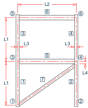
- L1 = 15 ft
- L2 = 20 ft
- L3 = 7 in
- L4 = 6 in
Actual input is shown in bold lettering followed by explanation.
STAAD PLANE TEST FOR MEMBER OFFSETS
Every input has to start with the term STAAD. The term PLANE signifies that the structure is a plane frame structure and the geometry is defined through X and Y axes.
UNIT FT KIP
Defines the input units for the data that follows.
    JOINT COORD
    1  0.  0.  ;  2  20.  0.  ;  3  0.  15.
    4  20.  15.  ;  5  0.  30.  ;  6  20.  30.
Joint number followed by X and Y coordinates are provided above. Since this is a plane structure, the Z coordinates need not be provided.
    SUPPORT
    1 2 PINNED
Pinned supports are specified at joints 1 and 2. The word PINNED signifies that no moments will be carried by these supports.
    MEMB INCI
    1 1 3 2 ; 3 3 5 4
    5 3 4 ; 6 5 6 ; 7 1 4
Defines the members by the joints to which they are connected.
    MEMB PROP AMERICAN
    1 TO 4 TABLE ST W14X90
    5 6 TA ST W12X26
    7 TA LD L80608
Member properties are assigned from the American (AISC) steel table for all members. The word ST stands for standard single section. LD stands for long leg back-to-back double angle.
    UNIT INCH
    MEMB OFFSET
    5 6 START 7.0 0.0 0.0
    5 6 END -7.0 0.0 0.0
    7 END -7.0 -6.0 0.0
The preceding specification states that an OFFSET is located at the START/END joint of the members. The X, Y, and Z global coordinates of the offset distance from the corresponding incident joint are also provided. These attributes are applied to members 5, 6, and 7.
    DEFINE MATERIAL START
    ISOTROPIC STEEL
    E 29000.
    POISSON 0.3
    DENSITY 283e-006
    ALPHA 6e-006
    DAMP 0.03
    TYPE STEEL
    STRENGTH FY 36 FU 58 RY 1.5 RT 1.2
    END DEFINE MATERIAL
    CONSTANT
    MATERIAL STEEL ALL
The DEFINE MATERIAL command is used to specify material properties and the CONSTANT is used to assign the material to all members.
LOADING 1 WIND LOAD
Load case 1 is initiated followed by a title.
    JOINT LOAD
    3 FX 50. ; 5 FX 25.0
Load 1 contains joint loads at nodes 3 and 5. FX indicates that the load is a force in the global X direction.
PERFORM ANALYSIS
The above command is an instruction to perform the analysis.
    UNIT FT
    PRINT FORCES
    PRINT REACTIONS
The above PRINT commands are instructions for writing the member forces and support reactions to the output file. The preceding line causes the results to be written in the length unit of feet.
FINISH
This command terminates a STAAD run.
Input File
STAAD PLANE TEST FOR MEMBER OFFSETS
UNIT FT KIP
JOINT COORD
1 0. 0. ; 2 20. 0. ; 3 0. 15.
4 20. 15. ; 5 0. 30. ; 6 20. 30.
MEMB INCI
1 1 3 2; 3 3 5 4
5 3 4 ; 6 5 6 ; 7 1 4
MEMB PROP AMERICAN
1 TO 4 TABLE ST W14X90
5 6 TA ST W12X26
7 TA LD L80608
UNIT INCH
MEMB OFFSET
5 6 START 7.0 0.0 0.0
5 6 END  -7.0 0.0 0.0
7 END -7.0 -6.0 0.0
DEFINE MATERIAL START
ISOTROPIC STEEL
E 29000
POISSON 0.3
DENSITY 283e-006
ALPHA 6e-006
DAMP 0.03
TYPE STEEL
STRENGTH FY 36 FU 58 RY 1.5 RT 1.2
END DEFINE MATERIAL
CONSTANT
MATERIAL STEEL ALL
SUPPORT
1 2 PINNED
LOADING 1 WIND LOAD
JOINT LOAD
3 FX 50. ; 5 FX 25.0
PERFORM ANALYSIS
UNIT FT
PRINT FORCES
PRINT REACTIONS
FINISH
STAAD Output File
                                                                  PAGE NO.    1
             ****************************************************
             *                                                  *
             *           STAAD.Pro CONNECT Edition              *
             *           Version  22.12.00.***                  *
             *           Proprietary Program of                 *
             *           Bentley Systems, Inc.                  *
             *           Date=    OCT 27, 2022                  *
             *           Time=    15:10:23                      *
             *                                                  *
             *  Licensed to: Bentley Systems Inc                *
             ****************************************************
     1. STAAD PLANE TEST FOR MEMBER OFFSETS
INPUT FILE: US-7 Modeling Offset Connections in a Frame.STD
     2. UNIT FT KIP
     3. JOINT COORD
     4. 1 0. 0. ; 2 20. 0. ; 3 0. 15.
     5. 4 20. 15. ; 5 0. 30. ; 6 20. 30.
     6. MEMB INCI
     7. 1 1 3 2; 3 3 5 4
     8. 5 3 4 ; 6 5 6 ; 7 1 4
     9. MEMB PROP AMERICAN
    10. 1 TO 4 TABLE ST W14X90
    11. 5 6 TA ST W12X26
    12. 7 TA LD L80608
    13. UNIT INCH
    14. MEMB OFFSET
    15. 5 6 START 7.0 0.0 0.0
    16. 5 6 END  -7.0 0.0 0.0
    17. 7 END -7.0 -6.0 0.0
    18. DEFINE MATERIAL START
    19. ISOTROPIC STEEL
    20. E 29000
    21. POISSON 0.3
    22. DENSITY 283E-006
    23. ALPHA 6E-006
    24. DAMP 0.03
    25. TYPE STEEL
    26. STRENGTH FY 36 FU 58 RY 1.5 RT 1.2
    27. END DEFINE MATERIAL
    28. CONSTANT
    29. MATERIAL STEEL ALL
    30. SUPPORT
    31. 1 2 PINNED
    32. LOADING 1 WIND LOAD
    33. JOINT LOAD
    34. 3 FX 50. ; 5 FX 25.0
    35. PERFORM ANALYSIS
      TEST FOR MEMBER OFFSETS                                  -- PAGE NO.    2
            P R O B L E M   S T A T I S T I C S
            -----------------------------------
     NUMBER OF JOINTS          6  NUMBER OF MEMBERS       7
     NUMBER OF PLATES          0  NUMBER OF SOLIDS        0
     NUMBER OF SURFACES        0  NUMBER OF SUPPORTS      2
           Using 64-bit analysis engine.
           SOLVER USED IS THE IN-CORE ADVANCED MATH SOLVER
   TOTAL      PRIMARY LOAD CASES =     1, TOTAL DEGREES OF FREEDOM =      14
   TOTAL LOAD COMBINATION  CASES =     0  SO FAR.
    36. UNIT FT
    37. PRINT FORCES
  FORCES
      TEST FOR MEMBER OFFSETS                                  -- PAGE NO.    3
   MEMBER END FORCES    STRUCTURE TYPE = PLANE
   -----------------
   ALL UNITS ARE -- KIP  FEET     (LOCAL )
  MEMBER  LOAD  JT     AXIAL   SHEAR-Y  SHEAR-Z   TORSION     MOM-Y      MOM-Z
      1    1     1    -10.69     -4.61     0.00      0.00      0.00       3.56
                 3     10.69      4.61     0.00      0.00      0.00     -72.68
      2    1     2     75.00     -5.73     0.00      0.00      0.00       0.00
                 4    -75.00      5.73     0.00      0.00      0.00     -85.95
      3    1     3     -6.73     11.92     0.00      0.00      0.00     112.47
                 5      6.73    -11.92     0.00      0.00      0.00      66.37
      4    1     4      6.73     13.08     0.00      0.00      0.00     127.91
                 6     -6.73    -13.08     0.00      0.00      0.00      68.25
      5    1     3     66.53     -3.96     0.00      0.00      0.00     -37.49
                 4    -66.53      3.96     0.00      0.00      0.00     -37.16
      6    1     5     13.08     -6.73     0.00      0.00      0.00     -62.44
                 6    -13.08      6.73     0.00      0.00      0.00     -64.32
      7    1     1   -106.85     -0.46     0.00      0.00      0.00      -3.56
                 4    106.85      0.46     0.00      0.00      0.00      -7.64
   ************** END OF LATEST ANALYSIS RESULT **************
    38. PRINT REACTIONS
  REACTION
      TEST FOR MEMBER OFFSETS                                  -- PAGE NO.    4
   SUPPORT REACTIONS -UNIT KIP  FEET    STRUCTURE TYPE = PLANE
   -----------------
 JOINT  LOAD   FORCE-X   FORCE-Y   FORCE-Z     MOM-X     MOM-Y     MOM Z
      1    1    -80.73    -75.00      0.00      0.00      0.00      0.00
      2    1      5.73     75.00      0.00      0.00      0.00      0.00
   ************** END OF LATEST ANALYSIS RESULT **************
    39. FINISH
             *********** END OF THE STAAD.Pro RUN ***********
               **** DATE= OCT 27,2022   TIME= 15:10:24 ****
      TEST FOR MEMBER OFFSETS                                  -- PAGE NO.    5
         ************************************************************
         *   For technical assistance on STAAD.Pro, please visit    *
         *   http://www.bentley.com/en/support/                     *
         *                                                          *
         *   Details about additional assistance from               *
         *   Bentley and Partners can be found at program menu      *
         *   Help->Technical Support                                *
         *                                                          *
         *           Copyright (c) Bentley Systems, Inc.            *
         *                http://www.bentley.com                    *
         ************************************************************