EX. UK-11 Response Spectrum Analysis of a Frame
Dynamic analysis (Response Spectrum) is performed for a steel structure. Results of a static and dynamic analysis are combined. The combined results are then used for steel design.
This problem is installed with the program by default to C:\Users\Public\Public Documents\STAAD.Pro CONNECT Edition\Samples\Sample Models\UK\UK-11 Response Spectrum Analysis of a Frame.STD when you install the program.
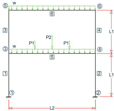
- L1 = 3 m, L2 = 6 m
- w = 22.5 kN/m
- P1 = 25 kN, P2 = 37.5 kN
Actual input is shown in bold lettering followed by explanation.
STAAD PLANE RESPONSE SPECTRUM ANALYSIS
Every input has to start with the term STAAD. The term PLANE signifies that the structure is a plane frame structure and the geometry is defined through X and Y axes.
UNIT METER KNS
Defines the input units for the data that follows.
    JOINT COORDINATES
    1 0.0 0.0 0.0 ; 2 6.0 0.0 0.0
    3 0.0 3.0 0.0 ; 4 6.0 3.0 0.0
    5 0.0 6.0 0.0 ; 6 6.0 6.0 0.0
Joint number followed by X, Y and Z coordinates are provided above. Since this is a plane structure, the Z coordinates are all the same, in this case, zeros.
    MEMBER INCIDENCES
    1 1 3 ; 2 2 4 ; 3 3 5 ; 4 4 6
    5 3 4 ; 6 5 6
Defines the members by the joints to which they are connected.
    MEMBER PROPERTIES BRITISH
    1 TO 4 TA ST UC254X254X73
    5 TA ST UB305X165X54
    6 TA ST UB203X133X30
Properties for all members are assigned from the British steel table. The word ST stands for standard single section.
    SUPPORTS
    1 2 FIXED
Fixed supports are specified at joints 1 and 2.
    UNIT MMS
    DEFINE MATERIAL START
    ISOTROPIC STEEL
    E 210
    POISSON 0.3
    DENSITY 7.6977e-008
    ALPHA 6e-006
    DAMP 0.03
    TYPE STEEL
    STRENGTH FY 0.24821 FU 0.399894 RY 1.5 RT 1.2
    END DEFINE MATERIAL
    CONSTANTS
    MATERIAL STEEL ALL
Material constants such as E (modulus of elasticity), Poisson’s ratio and density (DEN) are specified above. Length unit is changed from METER to MMS to facilitate the input.
CUT OFF MODE SHAPE 2
The number of mode shapes to be considered in dynamic analysis is set to 2. Without the above command, this will be set to the default. See TR.30.1 Cut-Off Frequency, Mode Shapes, or Time .
    * LOAD 1 WILL BE STATIC LOAD
    UNIT METER
    LOAD 1 DEAD AND LIVE LOADS
Load case 1 is initiated followed by a title. Prior to this, the length unit is changed to METER for specifying distributed member loads. A line starting with an asterisk (*) mark indicates a comment line.
SELFWEIGHT Y -1.0
The above command indicates that the selfweight of the structure acting in the global Y direction is part of this load case. The factor of -1.0 is meant to indicate that the load acts opposite to the positive direction of global Y, hence downwards.
    MEMBER LOADS
    5 CON GY -25.0 1.8
    5 CON GY -37.5 3.0
    5 CON GY -25.0 4.2
    5 6 UNI Y -22.5
Load 1 contains member loads also. GY indicates that the load is in the global Y direction while Y indicates local Y direction. The word UNI stands for uniformly distributed load while CON stands for concentrated load. GY is followed by the value of the load and the distance at which it is applied.
    * NEXT LOAD WILL BE RESPONSE SPECTRUM LOAD
    * WITH MASSES PROVIDED IN TERMS OF LOAD.
    LOAD 2 SEISMIC LOADING
The two lines which begin with the asterisk are comment lines which tell us the purpose of the next load case. Load case 2 is then initiated along with an optional title. This will be a dynamic load case. Permanent masses will be provided in the form of loads. These masses (in terms of loads) will be considered for the eigensolution. Internally, the program converts these loads to masses, hence it is best to specify them as absolute values (without a negative sign). Also, the direction (X, Y, Z etc.) of the loads will correspond to the dynamic degrees of freedom in which the masses are capable of vibrating. In a PLANE frame, only X and Y directions need to be considered. In a SPACE frame, masses (loads) should be provided in all three (X, Y and Z) directions if they are active along all three. The user has the freedom to restrict one or more directions.
    SELFWEIGHT X 1.0
    SELFWEIGHT Y 1.0
The above commands indicate that the selfweight of the structure acting in the global X and Y directions with a factor of 1.0 is taken into consideration for the mass matrix.
    MEMBER LOADS
    5 CON GX 25.0 1.8
    5 CON GY 25.0 1.8
    5 CON GX 37.5 3.0
    5 CON GY 37.5 3.0
    5 CON GX 25.0 4.2
    5 CON GY 25.0 4.2
The mass matrix will also consist of terms derived from the above member loads. GX and GY indicate that the load, and hence the resulting mass, is capable of vibration along the global X and Y directions. The word CON stands for concentrated load. Concentrated forces of 25, 37.5, and 25 kNs are located at 1.8m, 3.0m and 4.2m from the start of member 5.
    SPECTRUM CQC EURO X 1.0 ACC DAMP 0.05
    SOIL TYPE C ALPHA 0.15 Q 1.5
The SPECTRUM command specifies a Eurocode 8 2004 seismic response spectrum load. The modal responses will be combined using the CQC method. Here, the spectrum effect is in the global X direction with a factor of 1.0. EC8 2004 response spectra are always given in terms of acceleration (ACC). A damping ratio of 0.05 (5%) is used. The second line then gives the soil type along with the alpha ratio and behavior factor, Q.
    LOAD COMBINATION 3
    1 0.75 2 0.75
    LOAD COMBINATION 4
    1 0.75 2 -0.75
In a response spectrum analysis, the sign of the forces cannot be determined, and hence are absolute numbers. Consequently, to account for the fact that the force could be positive or negative, it is necessary to create 2 load combination cases. That is what is being done above. Load combination case no. 3 consists of the sum of the static load case (1) with the positive direction of the dynamic load case (2). Load combination case no. 4 consists of the sum of the static load case (1) with the negative direction of the dynamic load case (2). In both cases, the result is factored by 0.75.
PERFORM ANALYSIS PRINT MODE SHAPES
This command instructs the program to proceed with the analysis. The PRINT command instructs the program to print mode shape values.
PRINT ANALYSIS RESULTS
Displacements, reactions and member forces are recorded in the output file using the above command.
    LOAD LIST 1 3 4
    PARAMETER
    CODE EN 1993-1-1:2005
    NA 1
    SELECT ALL
A steel design in the form of a member selection is performed based on the rules of the Eurocode 8 code using the UK national annex. Only the member forces resulting from load cases 1, 3 and 4 will be considered for these calculations.
FINISH
This command terminates the STAAD run.
Input File
STAAD PLANE RESPONSE SPECTRUM ANALYSIS
UNIT METER KNS
JOINT COORDINATES
1 0.0 0.0 0.0 ; 2 6.0 0.0 0.0
3 0.0 3.0 0.0 ; 4 6.0 3.0 0.0
5 0.0 6.0 0.0 ; 6 6.0 6.0 0.0
MEMBER INCIDENCES
1 1 3 ; 2 2 4 ; 3 3 5 ; 4 4 6
5 3 4 ; 6 5 6
MEMBER PROPERTIES BRITISH
1 TO 4 TA ST UC254X254X73
5 TA ST UB305X165X54
6 TA ST UB203X133X30
SUPPORTS
1 2 FIXED
UNIT MMS
DEFINE MATERIAL START
ISOTROPIC STEEL
E 210
POISSON 0.3
DENSITY 7.6977e-008
ALPHA 6e-006
DAMP 0.03
TYPE STEEL
STRENGTH FY 0.24821 FU 0.399894 RY 1.5 RT 1.2
END DEFINE MATERIAL
CONSTANTS
MATERIAL STEEL ALL
CUT OFF MODE SHAPE 2
*LOAD 1 WILL BE STATIC LOAD
UNIT METER
LOAD 1 DEAD AND LIVE LOADS
SELFWEIGHT Y -1.0
MEMBER LOADS
5 CON GY -25.0 1.8
5 CON GY -37.5 3.0
5 CON GY -25.0 4.2
5 6 UNI Y -22.5
* NEXT LOAD WILL BE RESPONSE SPECTRUM LOAD
* WITH MASSES PROVIDED IN TERMS OF LOAD.
LOAD 2 SEISMIC LOADING
SELFWEIGHT X 1.0
SELFWEIGHT Y 1.0
MEMBER LOADS
5 CON GX 25.0 1.8
5 CON GY 25.0 1.8
5 CON GX 37.5 3.0
5 CON GY 37.5 3.0
5 CON GX 25.0 4.2
5 CON GY 25.0 4.2
SPECTRUM CQC EURO X 1.0 ACC DAMP 0.05
SOIL TYPE C ALPHA 0.15 Q 1.5
LOAD COMBINATION 3
1 0.75 2 0.75
LOAD COMBINATION 4
1 0.75 2 -0.75
PERFORM ANALYSIS PRINT MODE SHAPES
PRINT ANALYSIS RESULTS
LOAD LIST 1 3 4
PARAMETER
CODE EN 1993-1-1:2005
NA 1
SELECT ALL
FINISH
STAAD Output File
PAGE NO. 1 **************************************************** * * * STAAD.Pro CONNECT Edition * * Version 22.12.00.*** * * Proprietary Program of * * Bentley Systems, Inc. * * Date= OCT 27, 2022 * * Time= 15: 7: 3 * * * * Licensed to: Bentley Systems Inc * **************************************************** 1. STAAD PLANE RESPONSE SPECTRUM ANALYSIS INPUT FILE: UK-11 Response Spectrum Analysis of a Frame.STD 2. UNIT METER KNS 3. JOINT COORDINATES 4. 1 0.0 0.0 0.0 ; 2 6.0 0.0 0.0 5. 3 0.0 3.0 0.0 ; 4 6.0 3.0 0.0 6. 5 0.0 6.0 0.0 ; 6 6.0 6.0 0.0 7. MEMBER INCIDENCES 8. 1 1 3 ; 2 2 4 ; 3 3 5 ; 4 4 6 9. 5 3 4 ; 6 5 6 10. MEMBER PROPERTIES BRITISH 11. 1 TO 4 TA ST UC254X254X73 12. 5 TA ST UB305X165X54 13. 6 TA ST UB203X133X30 14. SUPPORTS 15. 1 2 FIXED 16. UNIT MMS 17. DEFINE MATERIAL START 18. ISOTROPIC STEEL 19. E 210 20. POISSON 0.3 21. DENSITY 7.6977E-008 22. ALPHA 6E-006 23. DAMP 0.03 24. TYPE STEEL 25. STRENGTH FY 0.24821 FU 0.399894 RY 1.5 RT 1.2 26. END DEFINE MATERIAL 27. CONSTANTS 28. MATERIAL STEEL ALL 29. CUT OFF MODE SHAPE 2 30. *LOAD 1 WILL BE STATIC LOAD 31. UNIT METER 32. LOAD 1 DEAD AND LIVE LOADS 33. SELFWEIGHT Y -1.0 34. MEMBER LOADS 35. 5 CON GY -25.0 1.8 36. 5 CON GY -37.5 3.0 37. 5 CON GY -25.0 4.2 38. 5 6 UNI Y -22.5 RESPONSE SPECTRUM ANALYSIS -- PAGE NO. 2 39. * NEXT LOAD WILL BE RESPONSE SPECTRUM LOAD 40. * WITH MASSES PROVIDED IN TERMS OF LOAD. 41. LOAD 2 SEISMIC LOADING 42. SELFWEIGHT X 1.0 43. SELFWEIGHT Y 1.0 44. MEMBER LOADS 45. 5 CON GX 25.0 1.8 46. 5 CON GY 25.0 1.8 47. 5 CON GX 37.5 3.0 48. 5 CON GY 37.5 3.0 49. 5 CON GX 25.0 4.2 50. 5 CON GY 25.0 4.2 51. SPECTRUM CQC EURO X 1.0 ACC DAMP 0.05 52. SOIL TYPE C ALPHA 0.15 Q 1.5 53. LOAD COMBINATION 3 54. 1 0.75 2 0.75 55. LOAD COMBINATION 4 56. 1 0.75 2 -0.75 57. PERFORM ANALYSIS PRINT MODE SHAPES P R O B L E M S T A T I S T I C S ----------------------------------- NUMBER OF JOINTS 6 NUMBER OF MEMBERS 6 NUMBER OF PLATES 0 NUMBER OF SOLIDS 0 NUMBER OF SURFACES 0 NUMBER OF SUPPORTS 2 Using 64-bit analysis engine. SOLVER USED IS THE IN-CORE ADVANCED MATH SOLVER TOTAL PRIMARY LOAD CASES = 2, TOTAL DEGREES OF FREEDOM = 12 TOTAL LOAD COMBINATION CASES = 2 SO FAR. ***NOTE: MASSES DEFINED UNDER LOAD# 2 WILL FORM THE FINAL MASS MATRIX FOR DYNAMIC ANALYSIS. EIGEN METHOD : SUBSPACE ------------------------- NUMBER OF MODES REQUESTED = 2 NUMBER OF EXISTING MASSES IN THE MODEL = 8 NUMBER OF MODES THAT WILL BE USED = 2 *** EIGENSOLUTION : ADVANCED METHOD *** RESPONSE SPECTRUM ANALYSIS -- PAGE NO. 3 CALCULATED FREQUENCIES FOR LOAD CASE 2 MODE FREQUENCY(CYCLES/SEC) PERIOD(SEC) 1 5.178 0.19312 2 19.435 0.05145 RESPONSE SPECTRUM ANALYSIS -- PAGE NO. 4 MODE SHAPES ----------- JOINT MODE X-TRANS Y-TRANS Z-TRANS X-ROTAN Y-ROTAN Z-ROTAN 1 1 0.00000 0.00000 0.00000 0.000E+00 0.000E+00 0.000E+00 2 1 0.00000 0.00000 0.00000 0.000E+00 0.000E+00 0.000E+00 3 1 0.58345 0.00218 0.00000 0.000E+00 0.000E+00 -3.862E-03 4 1 0.58345 -0.00218 0.00000 0.000E+00 0.000E+00 -3.862E-03 5 1 1.00000 0.00251 0.00000 0.000E+00 0.000E+00 -2.794E-03 6 1 1.00000 -0.00251 0.00000 0.000E+00 0.000E+00 -2.794E-03 MODE SHAPES ----------- JOINT MODE X-TRANS Y-TRANS Z-TRANS X-ROTAN Y-ROTAN Z-ROTAN 1 2 0.00000 0.00000 0.00000 0.000E+00 0.000E+00 0.000E+00 2 2 0.00000 0.00000 0.00000 0.000E+00 0.000E+00 0.000E+00 3 2 -0.07065 0.00282 0.00000 0.000E+00 0.000E+00 -2.798E-03 4 2 -0.07065 -0.00282 0.00000 0.000E+00 0.000E+00 -2.798E-03 5 2 1.00000 0.00400 0.00000 0.000E+00 0.000E+00 -9.739E-03 6 2 1.00000 -0.00400 0.00000 0.000E+00 0.000E+00 -9.739E-03 RESPONSE SPECTRUM LOAD 2 RESPONSE LOAD CASE 2 MODAL WEIGHT (MODAL MASS TIMES g) IN KNS GENERALIZED MODE X Y Z WEIGHT 1 9.711083E+01 9.577115E-18 0.000000E+00 3.624621E+01 2 1.780698E+00 1.662500E-16 0.000000E+00 4.389139E+00 CQC MODAL COMBINATION METHOD USED. DYNAMIC WEIGHT X Y Z 9.889183E+01 9.889183E+01 0.000000E+00 KNS MISSING WEIGHT X Y Z -3.075424E-04 -9.889183E+01 0.000000E+00 KNS MODAL WEIGHT X Y Z 9.889153E+01 1.758271E-16 0.000000E+00 KNS RESPONSE SPECTRUM ANALYSIS -- PAGE NO. 5 MODE ACCELERATION-G DAMPING ---- -------------- ------- 1 0.22191 0.05000 2 0.15815 0.05000 MODAL BASE ACTIONS MODAL BASE ACTIONS FORCES IN KNS LENGTH IN METE ----------------------------------------------------------- MOMENTS ARE ABOUT THE ORIGIN MODE PERIOD FX FY FZ MX MY MZ 1 0.193 21.55 0.00 0.00 0.00 0.00 -69.15 2 0.051 0.28 -0.00 0.00 0.00 0.00 0.42 PARTICIPATION FACTORS MASS PARTICIPATION FACTORS IN PERCENT BASE SHEAR IN KNS -------------------------------------- ------------------ MODE X Y Z SUMM-X SUMM-Y SUMM-Z X Y Z 1 98.20 0.00 0.00 98.199 0.000 0.000 21.55 0.00 0.00 2 1.80 0.00 0.00 100.000 0.000 0.000 0.28 0.00 0.00 --------------------------- TOTAL SRSS SHEAR 21.55 0.00 0.00 TOTAL 10PCT SHEAR 21.55 0.00 0.00 TOTAL ABS SHEAR 21.83 0.00 0.00 TOTAL CQC SHEAR 21.55 0.00 0.00 ***WARNING: NO RIGID FLOOR DIAPHRAGM EXISTS FOR THE STRUCTURE. RESULTS ON EARTHQUAKE MODE IN USER-INTERFACE MAY BE APPROXIMATE. WARNING : NO WELL DEFINED FLOOR LEVEL EXISTS FOR "STAAD SPACE" MODEL. CALCULATION OF STOREY SHEAR DUE TO MISSING MASS OR TORSION IGNORED. 58. PRINT ANALYSIS RESULTS ANALYSIS RESULTS RESPONSE SPECTRUM ANALYSIS -- PAGE NO. 6 JOINT DISPLACEMENT (CM RADIANS) STRUCTURE TYPE = PLANE ------------------ JOINT LOAD X-TRANS Y-TRANS Z-TRANS X-ROTAN Y-ROTAN Z-ROTAN 1 1 0.0000 0.0000 0.0000 0.0000 0.0000 0.0000 2 0.0000 0.0000 0.0000 0.0000 0.0000 0.0000 3 0.0000 0.0000 0.0000 0.0000 0.0000 0.0000 4 0.0000 0.0000 0.0000 0.0000 0.0000 0.0000 2 1 0.0000 0.0000 0.0000 0.0000 0.0000 0.0000 2 0.0000 0.0000 0.0000 0.0000 0.0000 0.0000 3 0.0000 0.0000 0.0000 0.0000 0.0000 0.0000 4 0.0000 0.0000 0.0000 0.0000 0.0000 0.0000 3 1 -0.0042 -0.0283 0.0000 0.0000 0.0000 -0.0017 2 0.1963 0.0007 0.0000 0.0000 0.0000 0.0005 3 0.1441 -0.0207 0.0000 0.0000 0.0000 -0.0009 4 -0.1504 -0.0218 0.0000 0.0000 0.0000 -0.0017 4 1 0.0042 -0.0283 0.0000 0.0000 0.0000 0.0017 2 0.1963 0.0007 0.0000 0.0000 0.0000 0.0005 3 0.1504 -0.0207 0.0000 0.0000 0.0000 0.0017 4 -0.1441 -0.0218 0.0000 0.0000 0.0000 0.0009 5 1 0.0163 -0.0390 0.0000 0.0000 0.0000 -0.0017 2 0.3366 0.0008 0.0000 0.0000 0.0000 0.0004 3 0.2647 -0.0286 0.0000 0.0000 0.0000 -0.0010 4 -0.2402 -0.0299 0.0000 0.0000 0.0000 -0.0015 6 1 -0.0163 -0.0390 0.0000 0.0000 0.0000 0.0017 2 0.3366 0.0008 0.0000 0.0000 0.0000 0.0004 3 0.2402 -0.0286 0.0000 0.0000 0.0000 0.0015 4 -0.2647 -0.0299 0.0000 0.0000 0.0000 0.0010 RESPONSE SPECTRUM ANALYSIS -- PAGE NO. 7 SUPPORT REACTIONS -UNIT KNS METE STRUCTURE TYPE = PLANE ----------------- JOINT LOAD FORCE-X FORCE-Y FORCE-Z MOM-X MOM-Y MOM Z 1 1 23.47 185.52 0.00 0.00 0.00 -21.57 2 10.78 4.78 0.00 0.00 0.00 20.25 3 25.69 142.72 0.00 0.00 0.00 -1.00 4 9.52 135.56 0.00 0.00 0.00 -31.37 2 1 -23.47 185.52 0.00 0.00 0.00 21.57 2 10.78 4.78 0.00 0.00 0.00 20.25 3 -9.52 142.72 0.00 0.00 0.00 31.37 4 -25.69 135.56 0.00 0.00 0.00 1.00 RESPONSE SPECTRUM ANALYSIS -- PAGE NO. 8 MEMBER END FORCES STRUCTURE TYPE = PLANE ----------------- ALL UNITS ARE -- KNS METE (LOCAL ) MEMBER LOAD JT AXIAL SHEAR-Y SHEAR-Z TORSION MOM-Y MOM-Z 1 1 1 185.52 -23.47 0.00 0.00 0.00 -21.57 3 -183.37 23.47 0.00 0.00 0.00 -48.85 2 1 4.78 10.78 0.00 0.00 0.00 20.25 3 4.78 10.78 0.00 0.00 0.00 12.08 3 1 142.72 -9.52 0.00 0.00 0.00 -1.00 3 -141.11 9.52 0.00 0.00 0.00 -45.70 4 1 135.56 -25.69 0.00 0.00 0.00 -31.37 3 -133.94 25.69 0.00 0.00 0.00 -27.58 2 1 2 185.52 23.47 0.00 0.00 0.00 21.57 4 -183.37 -23.47 0.00 0.00 0.00 48.85 2 2 4.78 10.78 0.00 0.00 0.00 20.25 4 4.78 10.78 0.00 0.00 0.00 12.08 3 2 142.72 25.69 0.00 0.00 0.00 31.37 4 -141.11 -25.69 0.00 0.00 0.00 27.58 4 2 135.56 9.52 0.00 0.00 0.00 1.00 4 -133.94 -9.52 0.00 0.00 0.00 45.70 3 1 3 70.53 -43.63 0.00 0.00 0.00 -65.87 5 -68.38 43.63 0.00 0.00 0.00 -65.02 2 3 0.74 0.74 0.00 0.00 0.00 0.44 5 0.74 0.74 0.00 0.00 0.00 2.20 3 3 53.45 -32.17 0.00 0.00 0.00 -49.07 5 -51.84 32.17 0.00 0.00 0.00 -50.42 4 3 52.35 -33.28 0.00 0.00 0.00 -49.73 5 -50.74 33.28 0.00 0.00 0.00 -47.12 4 1 4 70.53 43.63 0.00 0.00 0.00 65.87 6 -68.38 -43.63 0.00 0.00 0.00 65.02 2 4 0.74 0.74 0.00 0.00 0.00 0.44 6 0.74 0.74 0.00 0.00 0.00 2.20 3 4 53.45 33.28 0.00 0.00 0.00 49.73 6 -51.84 -33.28 0.00 0.00 0.00 47.12 4 4 52.35 32.17 0.00 0.00 0.00 49.07 6 -50.74 -32.17 0.00 0.00 0.00 50.42 5 1 3 -20.16 112.84 0.00 0.00 0.00 114.72 4 20.16 112.84 0.00 0.00 0.00 -114.72 2 3 0.00 4.01 0.00 0.00 0.00 12.02 4 0.00 4.01 0.00 0.00 0.00 12.02 3 3 -15.12 87.63 0.00 0.00 0.00 95.05 4 15.12 81.62 0.00 0.00 0.00 -95.05 RESPONSE SPECTRUM ANALYSIS -- PAGE NO. 9 MEMBER END FORCES STRUCTURE TYPE = PLANE ----------------- ALL UNITS ARE -- KNS METE (LOCAL ) MEMBER LOAD JT AXIAL SHEAR-Y SHEAR-Z TORSION MOM-Y MOM-Z 4 3 -15.12 81.62 0.00 0.00 0.00 77.03 4 15.12 87.63 0.00 0.00 0.00 -77.03 6 1 5 43.63 68.38 0.00 0.00 0.00 65.02 6 -43.63 68.38 0.00 0.00 0.00 -65.02 2 5 0.00 0.73 0.00 0.00 0.00 2.20 6 0.00 0.73 0.00 0.00 0.00 2.20 3 5 32.72 51.84 0.00 0.00 0.00 50.42 6 -32.72 50.74 0.00 0.00 0.00 -50.42 4 5 32.72 50.74 0.00 0.00 0.00 47.12 6 -32.72 51.84 0.00 0.00 0.00 -47.12 ************** END OF LATEST ANALYSIS RESULT ************** 59. LOAD LIST 1 3 4 60. PARAMETER 61. CODE EN 1993-1-1:2005 62. NA 1 63. SELECT ALL STEEL DESIGN STAAD.PRO MEMBER SELECTION - BS EN 1993-1-1:2005 ******************************************** NATIONAL ANNEX - NA to BS EN 1993-1-1:2005 PROGRAM CODE REVISION V1.14 BS_EC3_2005/1 RESPONSE SPECTRUM ANALYSIS -- PAGE NO. 10 ALL UNITS ARE - KNS METE (UNLESS OTHERWISE Noted) MEMBER TABLE RESULT/ CRITICAL COND/ RATIO/ LOADING/ FX MY MZ LOCATION ======================================================================= 1 ST UC152X152X37 (BRITISH SECTIONS) PASS EC-6.3.3-662 0.901 1 183.37 C 0.00 -48.85 3.00 2 ST UC152X152X37 (BRITISH SECTIONS) PASS EC-6.3.3-662 0.901 1 183.37 C 0.00 48.85 3.00 3 ST UC152X152X44 (BRITISH SECTIONS) PASS EC-6.3.3-662 0.851 1 70.53 C 0.00 -65.87 0.00 4 ST UC152X152X44 (BRITISH SECTIONS) PASS EC-6.3.3-662 0.851 1 70.53 C 0.00 65.87 0.00 5 ST UB305X165X54 (BRITISH SECTIONS) PASS EC-6.3.2 LTB 0.980 1 20.16 T 0.00 114.72 0.00 6 ST UB305X165X40 (BRITISH SECTIONS) PASS EC-6.3.3-662 0.972 1 43.63 C 0.00 65.02 0.00 ************** END OF TABULATED RESULT OF DESIGN ************** 64. FINISH **************************************************************************** **WARNING** SOME MEMBER SIZES HAVE CHANGED SINCE LAST ANALYSIS. IN THE POST PROCESSOR, MEMBER QUERIES WILL USE THE LAST ANALYSIS FORCES WITH THE UPDATED MEMBER SIZES. TO CORRECT THIS INCONSISTENCY, PLEASE DO ONE MORE ANALYSIS. FROM THE UPPER MENU, PRESS RESULTS, UPDATE PROPERTIES, THEN FILE SAVE; THEN ANALYZE AGAIN WITHOUT THE GROUP OR SELECT COMMANDS. **************************************************************************** *********** END OF THE STAAD.Pro RUN *********** **** DATE= OCT 27,2022 TIME= 15: 7: 3 **** RESPONSE SPECTRUM ANALYSIS -- PAGE NO. 11 ************************************************************ * For technical assistance on STAAD.Pro, please visit * * http://www.bentley.com/en/support/ * * * * Details about additional assistance from * * Bentley and Partners can be found at program menu * * Help->Technical Support * * * * Copyright (c) Bentley Systems, Inc. * * http://www.bentley.com * ************************************************************