TR.32.5 Prestress Load Specification
This command may be used to specify PRESTRESS loads on members of the structure.
General Format
MEMBER {PRESTRESS | POSTSTRESS } (LOAD)
memb-list FORCE f1 *{ ES f2 | EM f3 | EE f4 }
Where:
| Parameter | Description |
|---|---|
| FORCE f1 | Prestressing force. A positive value indicates precompression in the direction of the local x-axis. A negative value indicates pretension. |
| ES f2 | specifies eccentricity (from the centroid) of the prestress force at the start of the member. |
| EM f3 | specifies eccentricity (from the centroid) of the prestress force at the mid-point of the member. |
| EE f4 | specifies eccentricity (from the centroid) of the prestress force at the end of the member. |
Description
The first option, (MEMBER PRESTRESS LOAD), considers the effect of the prestressing force during its application. Thus, transverse shear generated at the ends of the member(s) subject to the prestressing force is transferred to the adjacent members.
The second option, (MEMBER POSTSTRESS LOAD), considers the effect of the existing prestress load after the prestressing operation. Thus, transverse shear at the ends of the member(s) subject to the prestressing force is not transferred to the adjacent members.
Example
MEMBER PRESTRESS
2 TO 7 11 FORCE 50.0
MEMBER POSTSTRESS
8 FORCE 30.0 ES 3.0 EM -6.0 EE 3.0
In the first example, a prestressing force of 50 force units is applied through the centroid (i.e., no eccentricity) of members 2 to 7 and 11. In the second example, a poststressing force of 30 force units is applied with an eccentricity of 3 length units at the start, -6.0 at the middle, and 3.0 at the end of member 8.
One of the limitations in using this command is that under any one load case, on any given member, a prestress or poststress load may be applied only once. If the given member carries multiple stressed cables or has a PRESTRESS and POSTSTRESS load condition, such a situation will have to be specified through multiple load cases for that member. See example below.
Incorrect Input:
LOAD 1
MEMBER PRESTRESS
6 7 FORCE 100 ES 2 EM -3 EE 2
6 FORCE 150 ES 3 EM -6 EE 3
PERFORM ANALYSIS
Correct Input:
LOAD 1 MEMBER PRESTRESS
6 7 FORCE 100 ES 2 EM -3 EE 2
LOAD 2
MEMBER PRESTRESS
6 FORCE 150 ES 3 EM -6 EE 3
LOAD COMBINATION 3
1 1.0 2 1.0
PERFORM ANALYSIS
Examples for Modeling Techniques
The following examples describe the partial input data for the members and cable profiles shown below.

JOINT COORD
1 0 0 ; 2 10 0
MEMBER INCI
1 1 2
…
UNIT …
LOAD 1
MEMBER POSTSTRESS
1 FORCE 100 ES 3 EM -3 EE 3
PERFORM ANALYSIS
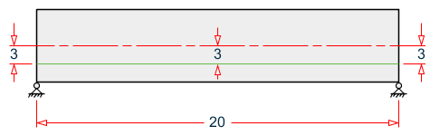
JOINT COORD
1 0 0 ; 2 20 0
MEMBER INCI
1 1 2
…
UNIT …
LOAD 1
MEMBER PRESTRESS
1 FORCE 100 ES -3 EM -3 EE -3
PERFORM ANALYSIS

JOINT COORD
1 0 0 ; 2 5 0 ; 3 15 0 0 ; 4 20 0
MEMBER INCI
1 1 2 ; 2 2 3 ; 3 3 4
…
UNIT …
LOAD 1
MEMBER PRESTRESS
1 FORCE 100 ES 3 EM 0 EE -3
2 FORCE 100 ES -3 EM -3 EE -3
3 FORCE 100 ES -3 EM 0 EE 3
PERFORM ANALYSIS
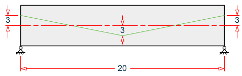
JOINT COORD
1 0 0 ; 2 10 0 ; 3 20 0 0
MEMBER INCI
1 1 2 ; 2 2 3
…
UNIT …
LOAD 1
MEMBER PRESTRESS
1 FORCE 100 ES 3 EM 0 EE -3
2 FORCE 100 ES -3 EM 0 EE 3
PERFORM ANALYSIS
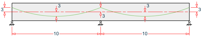
JOINT COORD
1 0 0 ; 2 10 0 ; 3 20 0 0
MEMBER INCI
1 1 2 ; 2 2 3
…
UNIT …
LOAD 1
MEMBER PRESTRESS
1 FORCE 100 ES 3 EM -3 EE 3
2 FORCE 100 ES 3 EM -3 EE 3
PERFORM ANALYSIS