Property dialog
Used to assign prismatic cross sections to members.
Opens when the Beam Profiles > Prismatic Profiles tool is selected in the Specifications group on the Specification ribbon tab.
Circle tab
| Setting | Description |
|---|---|
| YD | Section diameter. |
| Material | Check this box and select the material from the drop down list if the new member property tag should include the material constants. |
Rectangle tab
| Setting | Description |
|---|---|
| YD | Depth of the member in local y direction (local z direction with Z up). |
| ZD | Width of the member in the local z direction (local y direction with Z up). |
Tee tab
| Setting | Description |
|---|---|
| YD | Depth of the member in local y direction (local z direction with Z up). |
| ZD | Width of the flange, parallel to the local z-axis (local y-axis with Z up). |
| YB | Depth of the stem (web), parallel to the local y-axis (local b-axis with Z up). |
| ZB | Width of the stem (web), parallel to the local z-axis (local y-axis with Z up). |
Trapezoidal tab
| Setting | Description |
|---|---|
| YD | Depth of the member in local y direction (local z direction with Z up). |
| ZD | Top width, parallel to the local y-axis (local b-axis with Z up). |
| ZB | Bottom width, parallel to the local z-axis (local y-axis with Z up). |
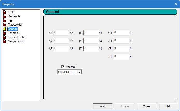
General tab
| Setting | Description |
|---|---|
| AX | Cross sectional area of the member. |
| AY | Effective shear area in local y-axis (local z-axis with Z up). |
| AZ | Effective shear area in local z-axis (local y-axis with Z up). |
| IX | Torsional constant. |
| IY | Moment of inertia about local y-axis (local z-axis with Z up). |
| IZ | Moment of inertia about local z-axis (usually major, local y-axis with Z up). |
| YD | Depth of the member in local y direction (local z-axis with Z up). Used as the diameter of section for circular members. |
| ZD | Depth of the member in local z direction (local y-axis with Z up). If ZD is not provided and YD is provided, the section will be assumed to be circular. |
| YB | Depth of stem for T-section parallel to the local y-axis (local z-axis with Z up). |
| ZB | Width of stem for Tee section or bottom width for trapezoidal section parallel to the local z-axis (local y-axis with Z up). |
Tapered I tab
| Setting | Description |
|---|---|
| F1 | Depth of section at start node. |
| F2 | Thickness of web. |
| F3 | Depth of section at end node. |
| F4 | Width of top flange. |
| F5 | Thickness of top flange. |
| F6 | Width of bottom flange. Defaults to F4 is zero. |
| F7 | Thickness of bottom flange. Defaults to F5 if zero. |
Tapered Tube tab
| Setting | Description |
|---|---|
| Type of Section | Select one of the profile shapes:
|
| d1 | Depth of section at start of member. |
| d2 | Depth of section at end of member. |
| th | Thickness of section (constant throughout the member length). |
Assign Profile tab
Used to instruct the program to select a suitable steel section based on a profile classification, such as beam, column, double-angle, etc.
| Setting | Description |
|---|---|
| Select Profile Specification | Specify a profile by selecting one of the options:
|