D5.E.1 General Comments
Principles of Limit States Design of Timber Structures are used as specified in the code.
Design per EC5 is limited to the prismatic, rectangular shapes only. There is no Eurocode-specific timber section database or library consisting of pre-defined shapes for analysis or for design. The feature of member selection is thus not applicable to this code.
The design philosophy of this specification is based on the concept of limit state design. Structures are designed and proportioned taking into consideration the limit states at which they would become unfit for their intended use. Two major categories of limit-state are recognized - ultimate and serviceability. The primary considerations in ultimate limit state design are strength and stability, while that in serviceability is deflection. Appropriate load and resistance factors are used so that a uniform reliability is achieved for all timber structures under various loading conditions and at the same time the chances of limits being surpassed are acceptably remote.
In the STAAD.Pro implementation, members are proportioned to resist the design loads without exceeding the limit states of strength, stability and serviceability. Accordingly, the most economic section is selected on the basis of the least weight criteria as augmented by the designer in specification of allowable member depths, desired section type, or other such parameters. The code checking portion of the program checks whether code requirements for each selected section are met and identifies the governing criteria.
The following sections describe the salient features of the STAAD.Pro implementation of EC 5. A detailed description of the design process along with its underlying concepts and assumptions is available in the specification document.
Axes convention in STAAD and EC5
STAAD.Pro defines the major axis of the cross-section as zz and the minor axis as yy. The longitudinal axis of the member is defined as x and joins the start joint of the member to the end with the same positive direction.
EC5, however, defines the principal cross-section axes in reverse to that of STAAD.Pro, but the longitudinal axis is defined in the same way. Both of these axes definitions follow the orthogonal right hand rule.
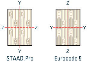
Axis conventions per STAAD and Eurocode 5
Determination of Factors
-
Kmod – Modification factor taking into account of Load-duration (LDC) and Moisture-content (Service Class - SCL). Reference Table 3.1 of EC-5-2004.
For "Solid Timber", the values are incorporated in the program.
-
γm – Partial factor for Material Property values. Reference Table 2.3 of EC-5-2004.
For "Solid Timber", the value of γm = 1.3 is incorporated in the program.
-
Kh – Size Factor.
For members, subjected to tension, whose maximum c/s dimension is less than the reference width in tension the characteristic strength in tension (ft0k) is to be increased by the factor Kh.
For members, subjected to bending, whose depth is less than reference depth in bending, the characteristic strength in bending (fmk) is to be increased by the factor Kh.
As per clause 3.2(3) of EC 5- 2004, for rectangular solid timber with a characteristic timber density ρk ≤ 700 kg/m3 the reference depth in bending or the reference width (maximum cross-sectional dimension) is 150 mm.
The value of Kh = Minimum of {(150/h) 0.2 and 1.3) for such solid timber is incorporated in the software. Please refer clause numbers 3.3 and 3.4 for the value of Kh for Glued laminated timber and Laminated veneer lumber respectively.
-
KC90 – Factor taking into account the load configuration, possibility of splitting and degree of compressive deformation.
For members, subjected to compression, perpendicular to the direction of grain alignment, this factor should be taken into account. Default value of 1 is used in STAAD.Pro. You may override the value. Please refer clause 6.1.5 of EC-5-2004 in this regard.
-
Km – Factor considering re-distribution of bending stress in cross section.
For members, subjected to bending, this factor is taken into account for stress checking. For rectangular section the value of Km is 0.7, and this value is incorporated in STAAD.Pro. You may override the value. Please refer clause 6.1.6 of EC-5-2004 in this regard.
-
Kshape – Factor depending on shape of cross section.
For members, subjected to torsional force, design torsional stress should be less than equal design shear strength multiplied by the factor Kshape. This factor is determined by STAAD.Pro internally using the guidelines of clause 6.1.8 of EC-5-2004.