G.17.4.2.2 Member Stiffness Matrix with Plastic Hinge
When numbers of springs are connected together in series, the force in each spring is the same. Here we will use the flexibility matrix rather than the stiffness matrix, which will enable us to avoid the intermediate displacements at the spring connections as variable.

Springs in a) parallel and b) series.
Thus write for each spring,
| Extension = flexibility x force |
and add up all the individual extensions to give
| Total extension = sum of flexibilities x force |
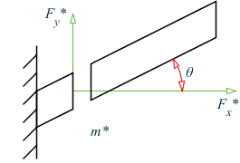
To demonstrate this idea, we will take one composite member as shown in Fig. This member is assumed to consist of a number of sections whose F matrices are known.
At first if we consider a case where end A is fixed and a load px is applied to end X, then by definition the displacement at X is given dX = eAX = FAX pX. This displacement is the sum of the displacements due to the strains in the individual sections.
Let us consider, the part KX of the member, lying between end 2 of section k and X.The load acting on the end of KX attached to the section k is equal to -HKXpX, and the load acting on end 2 of section k is HKXpX. Since A is fixed and AJ is considered rigid, end 1 of member k is effectively fixed, and the displacement of its end 2 is given by dK = eK = Fk p2A = Fk HKX pX .Now KX is a rigid member, and the displacements of its ends therefore satisfy the equation for rigid-body movement. Thus the displacement of X due to the strain induced in section k by the load pX at X is dXk = HtKX Fk HKX pX. Thus the flexibility matrix Fk of section k appears as HtKXFk HKX when viewed from the point X. Similar analysis may be applied to each section of AX, and adding up all the displacement contributions we obtain the complete flexibility matrix of AX in the form
| FAX = Σ HtKX·Fk·HKX |
Where the summation extends over all the sections making up the member Ax. Inversion of FAX gives the matrix KAX, and since the matrix HAX may be obtained either from the overall equilibrium of the member or by multiplying together all the H matrices of the sections the other stiffness matrices.
Semi-Rigid Joint Connections
When a member is attached to the joints at its ends by flexible connections, each of which transmits a moment proportional to the difference between the rotation of the end of the member and the rotation of the joint to which it is attached. Such joints occur in bolted frames, and in welded frames after the onset of plasticity.
Free body diagram of semi-rigid joint
To have a clear understanding, first we will describe it for a two-dimensional plane frame and then we will extend it to three-dimensional space frame.
Let us consider a frame of length Land flexural rigidity EI, whose ends 1 and 2 are attached to the rest of the frame by connections, which exert moment’s 4Eik1/L and 4Eik2/L respectively per unit difference in rotation. We ignore the length of each connection.
The displacement vector on the member side of the connection is given by the equation