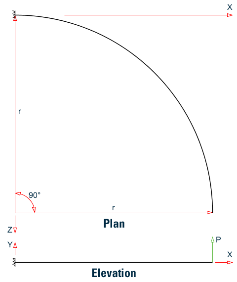
V. Curved Beam
To find the out-of-plane deflection and stress in a Circular cantilever member with a concentrated load at the free end.
Reference
Hand calculation using the following reference:
Timoshenko, S., Strength of Materials, Part I, D. Van Nostrand, 3rd Edition., 1955.
Problem
Calculate the displacement at the free end and the bending stress at the fixed end due to a concentrated load producing out–of–plane bending.
| E = 30×(10)6 psi |
| P = 50 lb |
| r = 100 in. |
Comparison
| Result | Theory | STAAD.Pro | Difference | Comments |
|---|---|---|---|---|
| Maximum deflection at free end (in.) | 2.648 | 2.64658 | negligible | |
| Principle stress (psi) | 6,366.0 | 6,638.1 | 4.3% | The result from a classical theory of a beam curved in plan is compared with the result from a piecewise linear set of beams, which closely resembles the behavior of a curved beam, but not exactly. Hence the difference in results. The difference may be further reduced to a certain level by discretizing the curved beam in more smaller subdivisions. |
STAAD Input
The file C:\Users\Public\Public Documents\STAAD.Pro CONNECT Edition\Samples\ Verification Models\01 Beams\Curved Beam.STDis typically installed with the program.
STAAD SPACE :A CURVED BEAM
START JOB INFORMATION
ENGINEER DATE 18-Sep-18
END JOB INFORMATION
*
*  REFERENCE: TIMOSHENKO, S., "STENGTH OF MATERIALS, PART I, ELEMENTARY
*             THEORY AND PROBLEMS", 3RD EDITION, D. VAN NOSTRAND CO.,
*             INC., NEW YORK, 1955.
*
INPUT WIDTH 72
UNIT INCHES POUND
JOINT COORDINATES
1 100 0 0; 2 99.619 0 -8.716; 3 98.481 0 -17.365; 4 96.593 0 -25.882;
5 93.969 0 -34.202; 6 90.631 0 -42.262; 7 86.603 0 -50;
8 81.915 0 -57.358; 9 76.604 0 -64.279; 10 70.711 0 -70.711;
11 64.279 0 -76.604; 12 57.358 0 -81.915; 13 50 0 -86.603;
14 42.262 0 -90.631; 15 34.202 0 -93.969; 16 25.882 0 -96.593;
17 17.365 0 -98.481; 18 8.716 0 -99.619; 19 0 0 -100;
MEMBER INCIDENCES
1 1 2; 2 2 3; 3 3 4; 4 4 5; 5 5 6; 6 6 7; 7 7 8; 8 8 9; 9 9 10;
10 10 11; 11 11 12; 12 12 13; 13 13 14; 14 14 15; 15 15 16; 16 16 17;
17 17 18; 18 18 19;
MEMBER PROPERTY AMERICAN
1 TO 18 PRIS AX 3.14 IX 1.57 IY 0.7854 IZ 0.7854 YD 2 ZD 2
DEFINE MATERIAL START
ISOTROPIC MATERIAL1
E 3e+07
POISSON 0.3
END DEFINE MATERIAL
CONSTANTS
MATERIAL MATERIAL1 ALL
SUPPORTS
19 FIXED
LOAD 1 POINT LOAD APPLIED AT THE FREE END
JOINT LOAD
1 FY 50
PERFORM ANALYSIS
PRINT MEMBER STRESSES LIST 18
PRINT JOINT DISPLACEMENTS LIST 1
FINISH
STAAD Output
  ALL UNITS ARE POUN/SQ INCH
 MEMB   LD  SECT    AXIAL    BEND-Y     BEND-Z   COMBINED  SHEAR-Y  SHEAR-Z
     18    1   .0      0.0        0.0    6082.7    6082.7     23.9      0.0
              1.0      0.0 C      0.0    6638.1    6638.1     23.9      0.0
   ************** END OF LATEST ANALYSIS RESULT **************
    39. PRINT JOINT DISPLACEMENTS LIST 1
  JOINT    DISPLACE LIST     1
      :A CURVED BEAM                                           -- PAGE NO.    4
   JOINT DISPLACEMENT (INCH RADIANS)    STRUCTURE TYPE = SPACE
   ------------------
 JOINT  LOAD   X-TRANS   Y-TRANS   Z-TRANS   X-ROTAN   Y-ROTAN   Z-ROTAN
      1    1    0.00000   2.64658   0.00000  -0.02438   0.00000   0.01076