AD.2005.1.1 Generation of Wind Pressure profile per ASCE 7-02
STAAD.Pro is now capable of generating the wind pressure profile for a structure in accordance with the ASCE-7-02 code. The pressure profile is the table of values of wind intensity versus height above ground.
The calculated pressure may then be applied on the structure to compute loads on members using the program’s built-in wind load generation algorithm for the closed as well as open-lattice type structures.
Description
The steps required to generate the wind pressure profile are as follows:
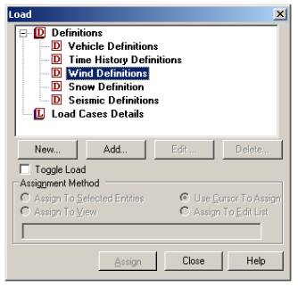
In the General | Load page (from the vertical tabs on the left-hand side), go to the Load dialog box on the right and select Wind Definitions as shown in the next figure.
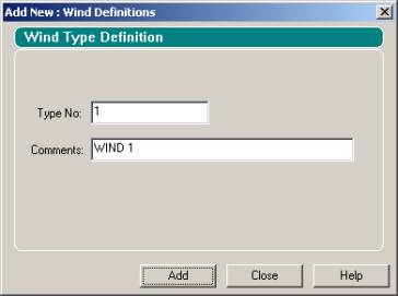
Click on the Add button to instantiate the Add New Wind Definitions dialog box shown in the next figure. Enter the Type No. which denotes a number by which the wind load type will be identified. Multiple wind types can be created in the same model. Click on the Add button within this dialog box and then click on Close.
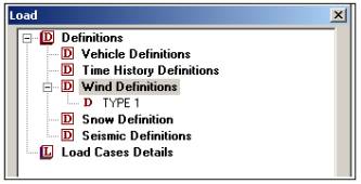
The newly created TYPE 1 wind definition will appear underneath Wind Definitions in the Load dialog box as shown below.
Select the TYPE 1 name in the tree control and click on the Add button. The dialog box shown below will prompt for the pressure profile (intensity) for this wind definition.
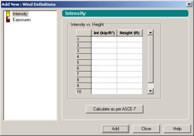
As we said earlier, the pressure profile is the table of wind intensity versus height above ground. If we know that, that information can be typed into the box above. But, our goal is to calculate that. Hence, we click on the button Calculate as per ASCE-7.
The ASCE-7: Wind Load dialog box shown below will appear.

The options shown in the dialog box are explained below:
Common Data

- ASCE - 7 -
- Depending on which version of the code to use, choose either 1995 or 2002.
- Building classification category
- Building classification category as obtained from Table 1-1 in SEI/ASCE 7-02. Category can be I, II, III or IV
- Basic Wind Speed
- Basic Wind Speed as described in section 6.5.4 of the SEI/ASCE 7-02 code.
- Exposure Category
- Exposure category as described in section 6.5.6.3 of the SEI/ASCE 7-02 code.
- Structure Type
- Select the type of structure that best fits the model from the available choices:
- Building structures
- Chimneys, Tanks and similar structures
- Solid Signs
- Open Signs
- Latticed Framework
- Trussed tower
The associated input pages will change depending on the selection of the type of structure.
- Consider Wind speed-up over hill or escarpment
- If there are isolated hills and escarpments that constitute abrupt changes in the general topography, the increase in speed can be considered as per section 6.5.7 in the SEI/ASCE 7-02 code. Select ‘Yes’ to consider wind speed-up over a hill or an escarpment and ‘No’ to ignore it.
- Type of Hill or Escarpment
- Select the type of hill, ridge or escarpment on which the structure is located, based on figure 6-4 of the SEI/ASCE 7-02 code. The options available are 2-D Escarpment, 2-D Ridge and 3-D Axisymmetric Hill.
- Height of Hill or Escarpment (H)
- Specify the height of the hill or escarpment relative to the upwind terrain (H in Figure 6-4 of the SEI /ASCE-7-02 code).
- Distance upwind of crest (Lh)
- Specify the distance upwind of crest to where the difference in general elevation is half the height of the hill or escarpment (Lh in Figure 6-4 of the SEI/ASCE-7-02 code).
- Distance from the crest to the building (x)
- Specify the distance from the crest to the building site. A negative value signifies that the distance is in the downwind direction (X in Figure 6-4 of the SEI/ASCE-7-02 code).
Main Building Data
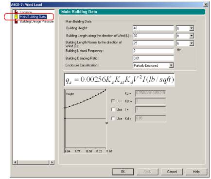
- Building Height
- The height above ground to the highest point on the roof surface.
- Building Length along the direction of Wind (L)
- Length of building measured along the direction of wind
- Building Length Normal to the direction of Wind (B)
- Length of building measured normal to the direction of wind
- Building Natural Frequency
- Specify the natural frequency of the building to calculate Gust Effect Factor.
- Building Damping Ratio
- Specify the damping ratio to calculate Gust Effect Factor.
- Building Damping Ratio
- Specify the damping ratio to calculate Gust Effect Factor.
- Enclosure Classification
- Classify the building as open building, partially enclosed or enclosed as per the provisions of section 6.2 of SEI/ASCE-7-02.
- Kz
- Velocity pressure exposure coefficient that is calculated by STAAD.Pro as per Table 6-3 of the SEI/ASCE-7-02 code.
- Kzt
- When wind speedup is considered, Kzt is calculated as per Eq 6-4 of the SEI/ASCE-7-02 code. Users can modify the value by checking the Use box and providing the required value in the edit box for Kzt.
- I
- Importance Factor I is considered as per section 6.2 of the SEI/ASCE-7-02 code. Users can enter their own value by checking the Use box and typing the required value in the edit box for I.
- Kd
- Wind directionality factor is calculated as per Table 6-4 of the SEI/ASCE-7-02 code. Users can modify the value by checking the Use box and typing the required value in the edit box for Kd.
The list of parameters explained earlier corresponds to the structure type called "Building Structures". When structure type is varied, some of those parameters change. Those parameters that are different are explained below for each type of structure.
Structure type: Chimney, Tank, and similar Structures
- Height (H)
- Height of the structure as defined by the term ‘h’ in Figure 6-19 of the SEI/ASCE 7-02 code.
- Least Horizontal Dimension (W)
- Smaller of the plan dimensions. In case the cross section of the structure in plan is circular, the diameter needs to be specified.
- Horizontal Cross-Section Type
- This is the cross section of the structure in plan as defined in Figure 6-19 of the SEI/ASCE 7-02 code. The available options include square with wind being normal to face or acting along the diagonal, hexagonal, octagonal and round.
- Depth of protruding elements such as ribs and spoilers (D’)
- For round type cross sections, depth of protruding elements need to be defined which is a measure of the surface roughness as indicated in Figure 6-19 of the SEI/ASCE 7-02 code.
- Cf
- Force coefficient that is calculated by STAAD.Pro as per Figure 6-19 of the SEI/ASCE 7-02 code. The parameter is used for calculation of design pressure. If desired, users can enter their own value for Cf by checking the Use box and typing the required value in the appropriate edit box.
Structure type: Solid Signs
- Height (H)
- Height of the structure which is used for calculating the height to width ratio as defined by the term ‘n’ in Figure 6-20 of the SEI/ASCE 7-02 code.
- Horizontal Dimension of Sign (M)
- Horizontal dimension of the solid sign
- Vertical Dimension of Sign (N)
- Vertical dimension of the solid sign. If the sign is at the ground level, the height (H) and vertical dimension (N) should both be specified the same value.
- Cf
- Force coefficient that is calculated by STAAD.Pro as per Figure 6-20 of the SEI/ASCE 7-02 code. The parameter is used for calculation of design pressure. If desired, users can enter their own value for Cf by checking the Use box and typing the required value in the appropriate edit box.
Structure type: Open Signs / Lattice Frame Work
- Ratio of Solid Area to Gross Area
- Ratio of solid area to gross area as indicated by the term e in Figure 6-21of the SEI/ASCE 7-02 code.
- Orientation of the members exposed to wind
- The type of member surfaces which are exposed to wind. Select flat-sided members or rounded members in Figure 6-21 of the SEI/ASCE 7-02 code.
- Diameter of typical round member
- Diameter for round members as defined by the term ‘D’ in Figure 6-21 of the SEI/ASCE 7-02 code.
Structure type: Trussed Tower
Building Design Pressure
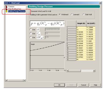
Building Wall to generate Wind Load on:
- Windward
- To generate the design wind pressure for the windward side, choose this option. The pressure will be calculated as per Equation 6-23 of the SEI/ASCE-7-02 code. The relevant equation is also displayed in the box just beneath the radio buttons.
- Leeward
- To generate the design wind pressure for the leeward side, choose this option. The pressure will be calculated as per Equation 6-23 of the SEI/ASCE-7-02 code. The relevant equation will be displayed in the box just beneath the radio buttons.
- Side Wall
- To generate the design wind pressure for the side wall, choose this option. As before, the pressure will be calculated as per Equation 6-23 of the SEI/ASCE-7-02 code. The relevant equation will be displayed in the box just beneath the radio buttons.
- G
- Gust effect factor calculated as per section 6.5.8 of the SEI/ASCE-7-02 code. Users can modify the value by checking the Use box and typing the required value in the edit box for G.
- Cp
- External pressure coefficient. The product of external pressure coefficient & gust effect factor is considered as per Figures 6-11 through 6-17 of the SEI/ASCE-7-02 code. Users can modify the value of Cp by checking the Use box and typing the required value in the edit box for Cp.
- GCpi
- Internal pressure Coefficients as per Figure 6-5 of the SEI/ASCE-7-02 code. Users can modify the value by checking the Use box and typing the required value in the edit box for GCpi.
The table on the right displays the intensities at various heights. Click on OK to arrive at the dialog box shown below.

Click on Add to add the load definition.
The defined wind loading can then be applied to the structure following the same procedure as in prior versions of the program. For details on the command syntax for generation of wind loads, refer to section 5.32.12: Generation of Loads from the STAAD Technical Reference Manual and example problem 15 in the Examples manual.