AD.2007-1001.1.2 Enhanced Grid Tool
- Allow multiple different grids to be created.
- Import a DXF file and use it as a template.
- Import grid files created in another STAAD.Pro model
Beams, plates (both triangular and quadrilateral) and 8 noded solid elements can be generated using the appropriate Snap/Grid Node tool.
When this function is launched, the following dialog is opened which will include a Default Grid. This grid will be of type ‘Linear’, there are also options to create Radial, Irregular and imported DXF grids which will be described later.
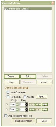
As new grids are added or modified, the information is stored in the STAAD.Pro data folder with a GRD extension that allows other STAAD files to re-use these defined grids.
The effect of the current grid settings are displayed in the graphics window, thus:

To change the settings of this grid click on the Edit button to display the current grid properties, e.g.:
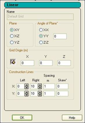
The current plane of the grid is set by selecting the required option. This can be rotated about one of the global planes by selecting the axis of rotation and setting the angle.
The origin of the grid is marked on the graphics with a small circle:

The location of the origin, specified in global co-ordinates, can either be defined explicitly in the given X, Y and Z co-ordinates, or it can be set to the co-ordinates of an existing node by clicking on the icon,  (the cursor changes to
  ) and then on the node itself in the graphical window. Note that at this point the origin co-ordinate is updated.
The construction lines are used to specify how many gridlines are created either side of the origin, the spacing between the gridlines and if there should be a skew in degrees along either axis.
Click on the OK button to accept these settings.
- Linear
- Radial
- Irregular
The type of grid required should be selected from the drop list of types available at the top of the property sheet.
Each new grid should be identified with a unique name for future reference. The functionality for each type of grid is thus:
Linear
The Default Grid defined above is a Linear Grid and thus see above for the settings of a Linear Grid.
Radial
The settings for a Radial grid are defined in the following window:

The Plane, Angle of Plane and Grid origin options are as for the Linear (or Default Grid).
The construction lines options
Start Angle, is the angle in degrees about the orthogonal axis to the plane from the axis first referred to in the definition of the plane. For examle, if the selected plane is X-Y, then the angle is measured about the Z axis (using the right hand rule) from the axis parallel to the X axis.
Sweep is the angle in degrees measured from the start angle which is divided into the selected number of Bays, thus:

Irregular
The settings for an Irregular grid are defined in the following window:

The origin is set as described above for both Regular and Radial grids.
The plane of the grid can either be set in one of the global planes X-Y, X-Z or Y-Z and rotated about one of the global axes. This method is identical to that described for the Regular or Radial Grids. Alternatively, the directions of the two axes can be specified as relative co-ordinates from the origin:

The gridlines are defined by the distance to the next gridline and the numbers separated with a space.
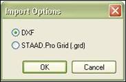
There are two import options that can be selected that can allow either DXF files or grids defined in another STAAD.Pro model (all but the default will be imported).
The option to import a DXF file will open the following dialog:
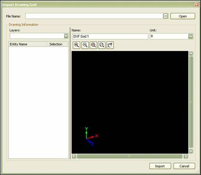
To select a DXF file click on the […] button and navigate to the required file.
The file will be opened and displayed in the preview window. Individual layers can be turned on and off from the Layers droplist. The individual entities in the selected layers are displayed and can be toggled on or off for import.
By clicking on an entity in the graphical window, the entity is highlighted in the table so that it can be turned off if required.
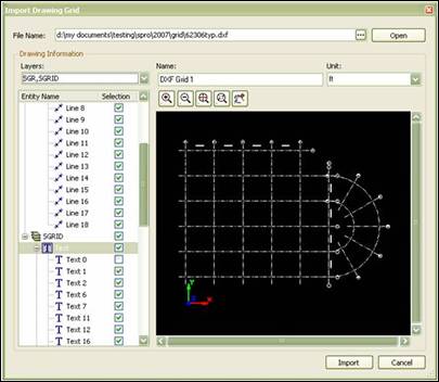
With the required entities selected, a suitable reference name supplied and unit selected, click on the Import button.
The data will be imported in the plane in which it was defined in the original DXF. However, if required this can be rotated about any of the global axes. Also, the origin of the grid can be located at any 3D co-ordinate.
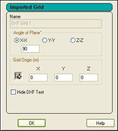
The option to Hide DXF text can be used to toggle the display of grid labels if they start clashing with the rest of the model. The grid is displayed thus (Note curved lines are currently not imported):

The DXF grid operates as the other forms of grid in that when the Snap Node/… button is clicked, nodes can be created at the ends and intersections of grid lines.
The second import option is to Import Grids previously defined in another STAAD.Pro model. Selecting this option opens a browse dialog box to identify a GRD file created by the Snap Node Grid tool. Note that GRD files are only created by STAAD.Pro 2007 (or later).


