D4.A.7 Slab and Wall Design
To design a slab or wall, it must be modeled using finite elements. The commands for specifying elements are in accordance with the relevant sections of the Technical Reference Manual.
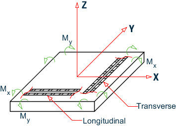
Elements are designed for the moments Mx and My using the same principles as those for beams in flexure. The width of the beam is assumed to be unity for this purpose. These moments are obtained from the element force output. The reinforcement required to resist Mx moment is denoted as longitudinal reinforcement and the reinforcement required to resist My moment is denoted as transverse reinforcement. The effective depth is calculated assuming #10 bars are provided. The parameters FYMAIN, FC, CLT, and CLB listed in D4.A.4 Design Parameters are relevant to slab design. Other parameters mentioned in Table 3A.1 are not applicable to slab design. The output consists only of area of steel required. Actual bar arrangement is not calculated because an element most likely represents just a fraction of the total slab area.