M. To generate plate mesh from corner nodes
To generate a finite element mesh by selecting corner nodes, use the following procedure.
This procedure is
used to immediately generate a mesh within a selection of vertices. If you
would like to investigate changing parameters prior to generating a mesh or to
add openings with the mesh, then you may want to use the procedure a
parametric mesh
model instead.
-
On the
Geometry ribbon tab, select the
tool in the
Plate group.

The mouse pointer changes to a mesh cursor. - Click the nodes that will form the vertices of the mesh area, in either a clockwise or counter clockwise order.
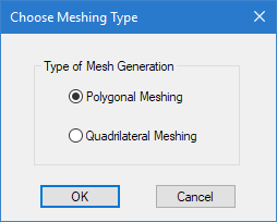
- When you have select the corner nodes, either: The Choose Meshing Type dialog opens.
-
Select the type of meshing to use and then click
OK.
- Polygonal Meshing
- Only triangular elements will be created
- Quadrilateral Meshing
- This will create principally four sided elements, but where the geometry dictates, some places may require triangular elements.
- Review the mesh vertices:
- Click OK. The specified area within the vertices is meshed.