V.IBC 2018 Static Seismic T Less Than 0.5
Verify the program-calculated base shear and its distribution along the height of a three-story frame by using the equivalent lateral force method per IBC 2018. Also, verify the torsional moments to which the floors are subjected to, considering inherent as well as accidental torsion.
Details
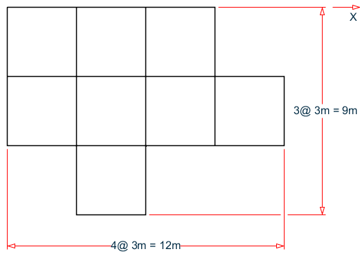
A three-story structure is subject to a seismic load from the +X direction. The time period of the structure used is its calculated Rayleigh frequency (taken from STAAD.Pro output).
Assumptions
- Mapped MCER spectral response acceleration parameter at short period, Ss = 2.02
- Mapped MCER spectral response acceleration parameter at a period of 1 s, S1 = 0.795
- Risk Category – I (Hence, From Table 1.5-2, Importance Factor I = 1)
- Site Class – D (SCLASS 4)
- Response Modification Factor (RX & RZ) = 3
- Long-period Transition Time (TL)=12 s
- Seismic weight is composed of UDLs (magnitude -5 kN/m, direction GY) (defined in Reference Load Definition), incident on the beams
- The effect of shear deformation is neglected
Validation
Calculation of Base Shear
Based on Ss and S1, Fa = 1 (per table 11.4-1) and Fv = 1.7 (per table 11.4-2).
Hence:
| SMS = Fa x Ss = 1 x 2.02 = 2.02 | Eq. 11.4-1 |
| SDS = 2/3 × SMS = 1.347 | Eq. 11.4-3 |
| SM1 = Fv x S1 = 1.7 x 0.795 = 1.382 | Eq. 11.4-3 |
| SD1 = 2/3 × SM1 = 0.901 | Eq. 11.4-4 |
| Eq. 12.8-2 |
The time period of the structure is taken as the Rayleigh frequency of the structure (taken from the output file), TR = 0.201 s.
Height of the structure, h = 9 m.
For concrete moment-resisting frames, Ct = 0.0466 and x = 0.9 (per Table 12.8-2).
So the approximate time period, Ta = Ct×hx = 0.0466(9 m)0.9 = 0.3367 s
From Table 12.8-1, Cu = 1.4 (for SD1 > 0.4).
Cu × Ta = 0.4713 s
The time period used, T, is the lesser of TR and Cu×Ta , which is 0.201 s (< TL = 12 s).
| Eq. 12.8-3 |
|
(CS)min1 = 0.044 × SDS × I = 0.0592 | Eq. 12.8-5 |
Since S1 = 0.795 > 0.6g, equation 12.8-6 also needs to be considered for calculating the lower limit of Cs :
| Eq. 12.8-6 |
Therefore, (Cs)min = 0.1325 < Cs.
Cs = 0.4489
The seismic weight, W is taken as the total seismic weight of the beams: = 5 × 3 × 69 = 1,035 kN
So the total base shear, V = CS × W = 0.4489 × 1,035 = 464.6 kN
Vertical Distribution of Lateral Forces
Since, time period of the structure T = 0.201 s < 0.5 s, as per clause 12.8.3, k = 1.
Hence, from equation 12.8-11 and equation 12.8-12, we can find the lateral forces in different story levels, as follows:
| Story Level |
Wx
(kN) |
hx
(m) |
Wx×hx k | Lateral force at story level (kN) |
|
|---|---|---|---|---|---|
| Roof | 5 × 3 × 23 = 345 | 9 | 3,105 | 0.500 | 232.3 |
| 2nd | 345 | 6 | 2,070 | 0.333 | 154.9 |
| 1st | 345 | 3 | 1,035 | 0.167 | 77.40 |
| Σ | 1,035 | - | 6,210 | 1 | 464.6 |
Consideration of Inherent Torsion (Clause 12.8.4.1)
Floor Level – Roof (9 m)
From output file, CRZ = 3. 831 m and CMZ = 3.848 m
Hence, static eccentricity esi = CMZ - CRZ = 0.017 m
Floor Level – 2nd (6 m)
From output file , CRZ = 3.858 m and CMZ = 3.848 m
Hence, static eccentricity esi = CMZ - CRZ = -0.01 m
Floor Level – 1st (3 m)
From output file , CRZ = 3.902 m and CMZ = 3.848 m
Hence, static eccentricity esi = CMZ - CRZ = -0.054 m
Consideration of Accidental Torsion (Clause 12.8.4.2)
At all floor levels:
| 0.05 × Lz = 0.05 × 9m = 0.45 m |
| = |
Hence, total eccentricity to inherent and accidental torsion at roof level er = (0.45 + 0.017) = 0.467 m
Total eccentricity to inherent and accidental torsion at 2nd floor level e2 = (0.45 - 0.01) = 0.44 m
Total eccentricity to inherent and accidental torsion at 1st floor level e1 = (0.45 - 0.054) = 0.396 m
Total torsional moment at roof level = Froof × er = 232.3 x 0.467 = 108.48 kN·m
Total Torsional moment at 2nd floor level = F2nd × e2 = 154.867 x 0.44 = 68.141 kN·m
Total torsional moment at 1st floor level = F1st × e1 = 77.433 x 0.396 = 30.664 kN·m
Results
| Result Type | Reference | STAAD.Pro | Difference | Comments |
|---|---|---|---|---|
| Base shear, V (kN) | 464.6 | 464.6 | none | |
| Lateral force at roof level (kN) | 232.3 | 232.3 | negligible | |
| Lateral force at 2nd floor (kN) | 154.9 | 154.867 | negligible | |
| Lateral force at 1st floor (kN) | 77.4 | 77.433 | negligible | |
| Torsional moment at roof level (kN·m) | 108.48 | 108.523 | negligible | |
| Torsional moment at 2nd floor (kN·m) | 68.141 | 68.092 | negligible | |
| Torsional moment at 1st floor (kN·m) | 30.664 | 30.619 | negligible |
STAAD.Pro Input File
The file C:\Users\Public\Public Documents\STAAD.Pro CONNECT Edition\Samples\ Verification Models\06 Loading\IBC\IBC 2018 Static Seismic T Less Than 0.STD is typically installed with the program.
STAAD SPACE
START JOB INFORMATION
ENGINEER DATE 08-Mar-19
END JOB INFORMATION
*****************************************************************************
*This problem is created to verify the base shear, distribution of base shear
*And Inherent and Accidental Torsional Moment at different floor levels
*Of the Structure
*****************************************************************************
INPUT WIDTH 79
SET SHEAR
UNIT METER KN
JOINT COORDINATES
1 0 0 0; 2 0 3 0; 3 3 3 0; 4 3 0 0; 5 0 0 3; 6 0 3 3; 7 3 3 3; 8 3 0 3;
9 0 0 6; 10 0 3 6; 11 3 3 6; 12 3 0 6; 13 0 0 9; 14 0 3 9; 15 3 3 9; 16 3 0 9;
17 6 3 0; 18 6 0 0; 19 6 3 3; 20 6 0 3; 21 6 3 6; 22 6 0 6; 25 9 3 3; 26 9 0 3;
27 9 3 6; 28 9 0 6; 33 0 6 0; 34 3 6 0; 35 0 6 3; 36 3 6 3; 37 0 6 6; 38 3 6 6;
39 0 6 9; 40 3 6 9; 41 6 6 0; 42 6 6 3; 43 6 6 6; 45 9 6 3; 46 9 6 6; 49 0 9 0;
50 3 9 0; 51 0 9 3; 52 3 9 3; 53 0 9 6; 54 3 9 6; 55 0 9 9; 56 3 9 9; 57 6 9 0;
58 6 9 3; 59 6 9 6; 70 9 9 3; 71 9 9 6; 72 -3 0 0; 73 -3 3 0; 74 -3 0 3;
75 -3 3 3; 76 -3 0 6; 77 -3 3 6; 80 -3 6 0; 81 -3 6 3; 82 -3 6 6; 84 -3 9 0;
85 -3 9 3; 86 -3 9 6;
MEMBER INCIDENCES
1 1 2; 2 2 3; 3 3 4; 4 2 6; 5 3 7; 6 5 6; 7 6 7; 8 7 8; 9 6 10; 10 7 11;
11 9 10; 12 10 11; 13 11 12; 14 10 14; 15 11 15; 16 13 14; 17 14 15; 18 15 16;
19 3 17; 20 7 19; 21 11 21; 23 17 18; 24 17 19; 25 19 20; 26 19 21; 27 21 22;
30 19 25; 31 21 27; 32 25 26; 33 25 27; 34 27 28; 40 2 33; 41 3 34; 42 6 35;
43 7 36; 44 10 37; 45 11 38; 46 14 39; 47 15 40; 48 17 41; 49 19 42; 50 21 43;
52 25 45; 53 27 46; 56 33 34; 57 33 35; 58 34 36; 59 35 36; 60 35 37; 61 36 38;
62 37 38; 63 37 39; 64 38 40; 65 39 40; 66 34 41; 67 36 42; 68 38 43; 70 41 42;
71 42 43; 73 42 45; 74 43 46; 75 45 46; 79 33 49; 80 34 50; 81 35 51; 82 36 52;
83 37 53; 84 38 54; 85 39 55; 86 40 56; 87 41 57; 88 42 58; 89 43 59; 95 49 50;
96 49 51; 97 50 52; 98 51 52; 99 51 53; 100 52 54; 101 53 54; 102 53 55;
103 54 56; 104 55 56; 105 50 57; 106 52 58; 107 54 59; 109 57 58; 110 58 59;
128 45 70; 129 46 71; 132 58 70; 133 59 71; 134 70 71; 135 2 73; 136 6 75;
137 10 77; 139 33 80; 140 35 81; 141 37 82; 143 49 84; 144 51 85; 145 53 86;
147 72 73; 148 73 75; 149 74 75; 150 75 77; 151 76 77; 154 73 80; 155 75 81;
156 77 82; 158 80 81; 159 81 82; 161 80 84; 162 81 85; 163 82 86; 165 84 85;
166 85 86;
DEFINE MATERIAL START
ISOTROPIC CONCRETE
E 2.17185e+07
POISSON 0.17
DENSITY 23.5616
ALPHA 1e-05
DAMP 0.05
TYPE CONCRETE
STRENGTH FCU 27579
END DEFINE MATERIAL
MEMBER PROPERTY AMERICAN
1 TO 21 23 TO 27 30 TO 34 40 TO 50 52 53 56 TO 68 70 71 73 TO 75 79 TO 89 -
95 TO 107 109 110 128 129 132 TO 137 139 TO 141 143 TO 145 147 TO 151 154 -
155 TO 156 158 159 161 TO 163 165 166 PRIS YD 0.4 ZD 0.4
CONSTANTS
MATERIAL CONCRETE ALL
SUPPORTS
1 4 5 8 9 12 13 16 18 20 22 26 28 72 74 76 FIXED
DEFINE REFERENCE LOADS
LOAD R1 LOADTYPE Mass  TITLE REF LOAD CASE 1
MEMBER LOAD
2 4 5 7 9 10 12 14 15 17 19 TO 21 24 26 30 31 33 56 TO 68 70 71 73 TO 75 95 -
96 TO 107 109 110 132 TO 137 139 TO 141 143 TO 145 148 150 158 159 165 -
166 UNI GY -5
END DEFINE REFERENCE LOADS
FLOOR DIAPHRAGM
DIA 1 TYPE RIG HEI 3
DIA 2 TYPE RIG HEI 6
DIA 3 TYPE RIG HEI 9
DEFINE IBC 2018
SS 2.02 S1 0.795 I 1 RX 3 RZ 3 SCLASS 4 TL 12
LOAD 1 LOADTYPE Seismic  TITLE SL +X
IBC LOAD X 1 DEC 2 ACC 0.05
PERFORM ANALYSIS PRINT LOAD DATA
PRINT DIA CR
FINISH
STAAD.Pro Output
   *****************************************************************************
   * EQUIV. SEISMIC LOADS AS PER IBC 2018                                      *
   * PARAMETERS CONSIDERED FOR SUBSEQUENT LOAD GENERATION                      *
   *  SS =  2.020 S1 =  0.795 FA =  1.000 FV =  1.700                          *
   *  SDS =  1.347 SD1 =  0.901                                                *
   *****************************************************************************
    72. LOAD 1 LOADTYPE SEISMIC  TITLE SL +X
    73. IBC LOAD X 1 DEC 2 ACC 0.05
    74. PERFORM ANALYSIS PRINT LOAD DATA
            P R O B L E M   S T A T I S T I C S
            -----------------------------------
     NUMBER OF JOINTS         67  NUMBER OF MEMBERS     117
     NUMBER OF PLATES          0  NUMBER OF SOLIDS        0
     NUMBER OF SURFACES        0  NUMBER OF SUPPORTS     16
           Using 64-bit analysis engine.
           SOLVER USED IS THE IN-CORE ADVANCED MATH SOLVER
   TOTAL      PRIMARY LOAD CASES =     1, TOTAL DEGREES OF FREEDOM =     162
   TOTAL LOAD COMBINATION  CASES =     0  SO FAR.
      STAAD SPACE                                              -- PAGE NO.    4
   LOADING     1  LOADTYPE SEISMIC  TITLE SL +X
   -----------
   ************************************************************
   *  IBC 2018 SEISMIC LOAD ALONG X  :                        *
   *     CT =  0.047 Cu =  1.400 x =  0.9000                  *
   *  TIME PERIODS :                                          *
   *     Ta =  0.337 T =  0.201 Tuser = 0.000                 *
   *  TIME PERIOD USED (T) =  0.201                           *
   *  Cs LIMITS : LOWER =  0.133 UPPER =  1.492               *
   *  LOAD FACTOR          =  1.000                           *
   *  DESIGN BASE SHEAR    =  1.000 X  0.449 X      1035.00   *
   *                       =       464.60  KN                 *
   ************************************************************
   ************************************************************************
   ***NOTE: SEISMIC LOAD IS ACTING AT CENTER OF MASS FOR RIGID DIAPHRAGM.
            TORSION FROM STATIC ECCENTRICITY (esi) IS INCLUDED IN ANALYSIS.
            DYNAMIC ECCENTRICITY APPLIED = DEC - 1
   LOAD NO.:     1  DIRECTION : X   UNIT - METE
   STORY  LEVEL     DYN. ECC. (dec)     ACC. ECC. (aec)     DESIGN     ECC.
   -----  -----     ---------------     ---------------     ---------------
                      X         Z         X         Z         X         Z
                                                          dec + aec dec + aec
     1     3.00     -0.05     -0.05      0.60      0.45      0.00      0.40
     2     6.00      0.01     -0.01      0.60      0.45      0.00      0.44
     3     9.00      0.05      0.02      0.60      0.45      0.00      0.47
   ************************************************************************
    JOINT            LATERAL          TORSIONAL            LOAD -    1
                     LOAD (KN  )      MOMENT (KN  -METE) FACTOR -   1.000
    -----            -------          ---------
                                      DEC + AEC
      STAAD SPACE                                              -- PAGE NO.    5
       2     FX        5.050    MY        1.997
       3     FX        5.050    MY        1.997
       6     FX        6.733    MY        2.663
       7     FX        6.733    MY        2.663
      10     FX        6.733    MY        2.663
      11     FX        6.733    MY        2.663
      14     FX        3.367    MY        1.331
      15     FX        3.367    MY        1.331
      17     FX        3.367    MY        1.331
      19     FX        6.733    MY        2.663
      21     FX        5.050    MY        1.997
      25     FX        3.367    MY        1.331
      27     FX        3.367    MY        1.331
      73     FX        3.367    MY        1.331
      75     FX        5.050    MY        1.997
      77     FX        3.367    MY        1.331
                 -----------        -----------
          TOTAL =     77.433             30.619 AT LEVEL     3.000 METE
      33     FX       10.100    MY        4.441
      34     FX       10.100    MY        4.441
      35     FX       13.467    MY        5.921
      36     FX       13.467    MY        5.921
      37     FX       13.467    MY        5.921
      38     FX       13.467    MY        5.921
      39     FX        6.733    MY        2.961
      40     FX        6.733    MY        2.961
      41     FX        6.733    MY        2.961
      42     FX       13.467    MY        5.921
      43     FX       10.100    MY        4.441
      45     FX        6.733    MY        2.961
      46     FX        6.733    MY        2.961
      80     FX        6.733    MY        2.961
      81     FX       10.100    MY        4.441
      82     FX        6.733    MY        2.961
                 -----------        -----------
          TOTAL =    154.867             68.092 AT LEVEL     6.000 METE
      49     FX       15.150    MY        7.078
      50     FX       15.150    MY        7.078
      51     FX       20.200    MY        9.437
      52     FX       20.200    MY        9.437
      53     FX       20.200    MY        9.437
      54     FX       20.200    MY        9.437
      55     FX       10.100    MY        4.718
      56     FX       10.100    MY        4.718
      57     FX       10.100    MY        4.718
      58     FX       20.200    MY        9.437
      59     FX       15.150    MY        7.078
      70     FX       10.100    MY        4.718
      71     FX       10.100    MY        4.718
      84     FX       10.100    MY        4.718
      85     FX       15.150    MY        7.078
      86     FX       10.100    MY        4.718
      STAAD SPACE                                              -- PAGE NO.    6
                 -----------        -----------
          TOTAL =    232.300            108.523 AT LEVEL     9.000 METE
   ************ END OF DATA FROM INTERNAL STORAGE ************
    75. PRINT DIA CR
  DIA      CR
   ************************************************************
   CENTRE OF RIGIDITY     UNIT - METE
   ------------------     -----------
   DIAPHRAM      FL. LEVEL      X-COORDINATE      Z-COORDINATE
       1            3.000            2.393             3.902
       2            6.000            2.335             3.858
       3            9.000            2.299             3.831
   ************************************************************