V. Forces on a Propped Cantilever 2
To find deflections, stress and support reactions due to a uniform load on a beam with one end fixed and the other end supported by a roller.
Reference
Hand calculation using the following reference:
Roark, R.J., and Young, W.C., Formulas for Stress and Strain, 5th Edition, Page 109, Problem 23.
Problem
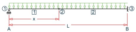
A horizontal beam of length = 100 in, area = 4 in2, height = 2 in, and moment of inertia = 1.3333 in4 is simply supported at one end and fixed at the other end (a "propped" cantilever). The beam is subjected to an arbitrary uniform loading. Determine the deflection, δ, at x = 42.15 in., the slope, θ, at end A, the maximum bending stress, σbend, in the beam, and the support reactions.
| E = 30×(10)6 psi |
| Density = 0.2821 lbs/in3 |
Propped cantilever beam model
Comparison
| Result | Theory | STAAD.Pro | Difference |
|---|---|---|---|
| Reaction at Node 1 (lb) | 42.31 | 42.31 | none |
| Reaction at Node 3 (lb) | 70.52 | 70.52 | none |
| Moment at Node 3 (in·lb) | 1,410.4 | 1410.4 | none |
| Bending Stress, σbend at Node 2 (psi) | 585.9 | 585.9 | none |
| Rotation at Node 1 (rad.) | -.000588 | -.00059 | none |
| Deflection at Node 2 (in.) | -0.01528 | -0.01528 | none |
STAAD Input
The file C:\Users\Public\Public Documents\STAAD.Pro CONNECT Edition\Samples\ Verification Models\01 Beams\Forces on a Propped Cantilever 2.STDis typically installed with the program.
STAAD PLANE :A FIXED-ROLLER BEAM
START JOB INFORMATION
ENGINEER DATE 18-Sep-18
END JOB INFORMATION
*
* REFERENCE: ROARK AND YOUNG, PAGE 109, NO. 23.
*
INPUT WIDTH 72
UNIT INCHES POUND
JOINT COORDINATES
1 0 0 0; 2 42.15 0 0; 3 100 0 0;
MEMBER INCIDENCES
1 1 2; 2 2 3;
MEMBER PROPERTY AMERICAN
1 2 PRIS AX 4 IZ 1.3333 YD 2
DEFINE MATERIAL START
ISOTROPIC MATERIAL1
E 3e+07
POISSON 0.290909
DENSITY 0.282072
END DEFINE MATERIAL
CONSTANTS
MATERIAL MATERIAL1 ALL
SUPPORTS
3 FIXED
1 PINNED
LOAD 1 SELF WEIGHT
SELFWEIGHT Y -1
PERFORM ANALYSIS
PRINT ANALYSIS RESULTS
PRINT MEMBER STRESSES ALL
FINISH
STAAD Output
   JOINT DISPLACEMENT (INCH RADIANS)    STRUCTURE TYPE = PLANE
   ------------------
 JOINT  LOAD   X-TRANS   Y-TRANS   Z-TRANS   X-ROTAN   Y-ROTAN   Z-ROTAN
      1    1    0.00000   0.00000   0.00000   0.00000   0.00000  -0.00059
      2    1    0.00000  -0.01528   0.00000   0.00000   0.00000  -0.00000
      3    1    0.00000   0.00000   0.00000   0.00000   0.00000   0.00000
      :A FIXED-ROLLER BEAM                                     -- PAGE NO.    4
   SUPPORT REACTIONS -UNIT POUN INCH    STRUCTURE TYPE = PLANE
   -----------------
 JOINT  LOAD   FORCE-X   FORCE-Y   FORCE-Z     MOM-X     MOM-Y     MOM Z
      3    1      0.00     70.52      0.00      0.00      0.00  -1410.36
      1    1      0.00     42.31      0.00      0.00      0.00      0.00
      :A FIXED-ROLLER BEAM                                     -- PAGE NO.    5
   MEMBER END FORCES    STRUCTURE TYPE = PLANE
   -----------------
   ALL UNITS ARE -- POUN INCH     (LOCAL )
  MEMBER  LOAD  JT     AXIAL   SHEAR-Y  SHEAR-Z   TORSION     MOM-Y      MOM-Z
      1    1     1      0.00     42.31     0.00      0.00      0.00       0.00
                 2      0.00      5.25     0.00      0.00      0.00     781.13
      2    1     2      0.00     -5.25     0.00      0.00      0.00    -781.13
                 3      0.00     70.52     0.00      0.00      0.00   -1410.36
   ************** END OF LATEST ANALYSIS RESULT **************
    31. PRINT MEMBER STRESSES ALL
  MEMBER   STRESSES ALL
      :A FIXED-ROLLER BEAM                                     -- PAGE NO.    6
  MEMBER STRESSES
  ---------------
  ALL UNITS ARE POUN/SQ INCH
 MEMB   LD  SECT    AXIAL    BEND-Y     BEND-Z   COMBINED  SHEAR-Y  SHEAR-Z
      1    1   .0      0.0        0.0       0.0       0.0     15.9      0.0
              1.0      0.0 C      0.0     585.9     585.9      2.0      0.0
      2    1   .0      0.0        0.0     585.9     585.9      2.0      0.0
              1.0      0.0 C      0.0    1057.8    1057.8     26.4      0.0